Fiber Amplifier/EDFA, Principle and Classification of Fiber Amplifier/EDFA
Fiber Amplifier Classification
There are three main types of optical amplifiers:
(1) Semiconductor Optical Amplifier (SOA);
(2) Fiber amplifiers doped with rare earth elements (erbium, thulium, praseodymium, rubidium, etc.), mainly erbium-doped fiber amplifiers (EDFA), thulium-doped fiber amplifiers (TDFA) and praseodymium-doped fiber amplifiers (PDFA);
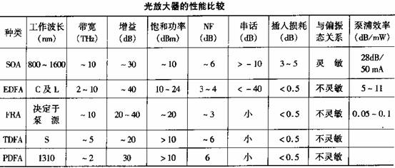
(3) Nonlinear fiber amplifiers, mainly fiber Raman amplifiers (FRA). The main performance comparison of these optical amplifiers is shown in Table

EDFA (Erbium Doped Fiber Amplifier)
Quartz optical fiber doped with rare earth elements (such as Nd, Er, Pr, Tm, etc.) can form a multi-level laser system, which can directly amplify the input signal light under the action of pump light. After providing appropriate feedback, it forms a fiber laser. The operating wavelength of Nd-doped fiber amplifier is 1060nm and 1330nm. Due to deviation from the optimal host port of optical fiber communication and other reasons, its development and application are limited. The operating wavelengths of EDFA and PDFA are respectively in the lowest loss (1550nm) and zero dispersion wavelength (1300nm) windows of optical fiber communication, and TDFA works in the S band, which are very suitable for optical fiber communication system applications. Especially EDFA, which has developed the fastest and has been put into practical use.
Principle of EDFA
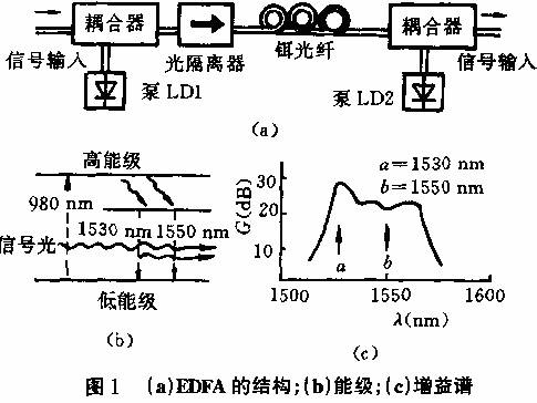
The basic structure of EDFA is shown in Figure 1 (a). It mainly consists of active media (erbium-doped quartz fiber with a length of about tens of meters, core diameter of 3-5 microns, doping concentration (25-1000) x10-6), pump light source (990 or 1480nm LD), optical coupler and optical isolator. Signal light and pump light can propagate in the same direction (co-directional pumping), opposite directions (reverse pumping) or both directions (bidirectional pumping) in erbium fiber. When signal light and pump light are injected into erbium fiber at the same time, erbium ions are excited to a high energy level under the action of pump light (Figure 1 (b), three-level system), and quickly decay to a metastable energy level. When returning to the ground state under the action of incident signal light, photons corresponding to the signal light are emitted, so that the signal is amplified. Figure 1 (c) shows its amplified spontaneous emission (ASE) spectrum, which has a large bandwidth (up to 20-40nm) and has two peaks, corresponding to 1530nm and 1550nm respectively.
The main advantages of EDFA are high gain, large bandwidth, high output power, high pump efficiency, low insertion loss, and insensitivity to polarization state.

Problems with optical amplifiers
Although the optical amplifier (especially EDFA) has many outstanding advantages, it is not an ideal amplifier. In addition to the additional noise that reduces the SNR of the signal, there are some other shortcomings, such as:
• Unflat gain spectrum within the amplifier bandwidth affects multi-channel amplification performance;
•When optical amplifiers are cascaded, the effects of ASE noise, fiber dispersion and nonlinear effects will accumulate.
These issues must be considered in application and system design.
Application of Optical Amplifiers in Fiber Optic Communication Systems
In fiber-optic communication systems, optical amplifiers can be used as power booster amplifiers for transmitters to increase transmission power, as preamplifiers for receivers to increase receiving sensitivity, and can also replace traditional optical-electrical-optical repeaters to extend transmission distances and achieve all-optical communication.
In optical fiber communication systems, the main factors limiting transmission distance are optical fiber loss and dispersion. Using narrow-spectrum light sources or working near the zero-dispersion wavelength will reduce the impact of optical fiber dispersion. This system does not require complete signal timing regeneration at each relay station (3R relay), and it is sufficient to directly amplify the optical signal with an optical amplifier (1R relay). Optical amplifiers can be used not only in long-distance trunk systems, but also in optical fiber distribution networks, especially in WDM systems, for simultaneous amplification of multiple channels.

1) Application of optical amplifiers in trunk optical fiber communication systems
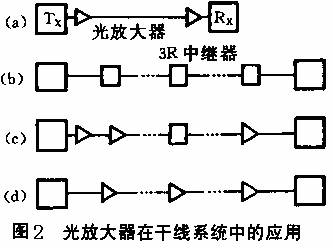
Figure 2 is a schematic diagram of the application of optical amplifiers in trunk fiber-optic communication systems. Figure (a) shows the use of optical amplifiers as transmitter power boost amplifiers and receiver preamplifiers, which doubles the unrelayed distance. For example, with EDFA, the transmission distance of a 1.8Gb/s system increases from 120km to 250km or even 400km. Figure 2 (b)-(d) shows the application of optical amplifiers in multi-relay systems; Figure (b) is the traditional 3R relay method; Figure (c) is a hybrid relay method of 3R repeaters and optical amplifiers; Figure (d) is an all-optical relay method; in an all-optical communication system, timing and regeneration circuits are not included, so it is bit-penetrating and has no "electronic bottle whiskers" restrictions. As long as the transmitting and receiving equipment at both ends is replaced, it is easy to upgrade from a low rate to a high rate, and the optical amplifier does not need to be replaced.
2) Application of optical amplifiers in fiber distribution networks
The high power output advantage of optical amplifiers (especially EDFA) is very useful in broadband distribution networks (such as CATV networks). Traditional CATV networks use coaxial cables and need to be amplified every few hundred meters. The service radius of the network is about 7km. The fiber-optic CATV network using optical amplifiers can not only greatly increase the number of distributed users, but also greatly expand the network diameter. Recent developments have shown that the fiber/coaxial cable hybrid (HFC) distribution network has the advantages of both and is very competitive.
Figure 3 shows an example of a fiber distribution network for 35 TV channels modulated by AM-VSB. The transmitter light source is a DFB-LD with a wavelength of 1550nm and an output power of 3.3dBm. A 4-level EDFA is used as a power distribution amplifier with an input power of about -6dBm and an output power of about 13dBm. The sensitivity of the optical receiver is -9.2dBm. After 4-level distribution, the total number of users reaches 4.2 million, and the network diameter is more than tens of kilometers. The weighted signal-to-noise ratio tested is greater than 45dB, and the EDFA does not cause a decrease in CSO.

Previous article:Preamplifier, what is the function and principle of preamplifier
Next article:What does rail-to-rail operational amplifier mean?
Recommended ReadingLatest update time:2024-11-16 14:50


- Popular Resources
- Popular amplifiers
-
 Operational Amplifier Practical Reference Handbook (Edited by Liu Changsheng, Zhao Mingying, Liu Xu, etc.)
 -
 A Complete Illustrated Guide to Operational Amplifier Applications (Written by Wang Zhenhong)
 -
 Design of isolated error amplifier chip for switching power supply_Zhang Rui
 -
 DAM medium wave transmitter high frequency power amplifier module test platform_Tian Tian
- High signal-to-noise ratio MEMS microphone drives artificial intelligence interaction
- Advantages of using a differential-to-single-ended RF amplifier in a transmit signal chain design
- ON Semiconductor CEO Appears at Munich Electronica Show and Launches Treo Platform
- ON Semiconductor Launches Industry-Leading Analog and Mixed-Signal Platform
- Analog Devices ADAQ7767-1 μModule DAQ Solution for Rapid Development of Precision Data Acquisition Systems Now Available at Mouser
- Domestic high-precision, high-speed ADC chips are on the rise
- Microcontrollers that combine Hi-Fi, intelligence and USB multi-channel features – ushering in a new era of digital audio
- Using capacitive PGA, Naxin Micro launches high-precision multi-channel 24/16-bit Δ-Σ ADC
- Fully Differential Amplifier Provides High Voltage, Low Noise Signals for Precision Data Acquisition Signal Chain
- Innolux's intelligent steer-by-wire solution makes cars smarter and safer
- 8051 MCU - Parity Check
- How to efficiently balance the sensitivity of tactile sensing interfaces
- What should I do if the servo motor shakes? What causes the servo motor to shake quickly?
- 【Brushless Motor】Analysis of three-phase BLDC motor and sharing of two popular development boards
- Midea Industrial Technology's subsidiaries Clou Electronics and Hekang New Energy jointly appeared at the Munich Battery Energy Storage Exhibition and Solar Energy Exhibition
- Guoxin Sichen | Application of ferroelectric memory PB85RS2MC in power battery management, with a capacity of 2M
- Analysis of common faults of frequency converter
- In a head-on competition with Qualcomm, what kind of cockpit products has Intel come up with?
- Dalian Rongke's all-vanadium liquid flow battery energy storage equipment industrialization project has entered the sprint stage before production
- Allegro MicroSystems Introduces Advanced Magnetic and Inductive Position Sensing Solutions at Electronica 2024
- Car key in the left hand, liveness detection radar in the right hand, UWB is imperative for cars!
- After a decade of rapid development, domestic CIS has entered the market
- Aegis Dagger Battery + Thor EM-i Super Hybrid, Geely New Energy has thrown out two "king bombs"
- A brief discussion on functional safety - fault, error, and failure
- In the smart car 2.0 cycle, these core industry chains are facing major opportunities!
- The United States and Japan are developing new batteries. CATL faces challenges? How should China's new energy battery industry respond?
- Murata launches high-precision 6-axis inertial sensor for automobiles
- Ford patents pre-charge alarm to help save costs and respond to emergencies
- New real-time microcontroller system from Texas Instruments enables smarter processing in automotive and industrial applications
- TouchGFX Design + HMI Design for HVAC Air Conditioning
- [Repost] 10 rules for PCB layout and wiring
- Switching Power Supply
- Dual-core communication exchanges data through shared memory ARM-side program learning
- Please recommend a newer rf development kit
- Triangle wave generating circuit
- [RT-Thread Reading Notes] Part 2 (1) Porting, Running and Thread Management
- Are you confused about gate driver selection? Download the latest selection guide
- Wish you all a happy Dragon Boat Festival
- Using MCU to implement speech recognition? MSP432 can do it!

 Operational Amplifier Practical Reference Handbook (Edited by Liu Changsheng, Zhao Mingying, Liu Xu, etc.)


 京公网安备 11010802033920号