The principle of interference suppression
Suppression jamming is an active jamming method that injects jamming signals into enemy radars so that the real target echo signal is drowned out by the jamming. It mainly generates broadband or narrowband active noise signals on the radar's tuning band, radiates in space to form a suppression jamming environment, and artificially transmits noise to the radar's receiver, increasing the noise level at its input end and reducing its signal-to-noise ratio, thereby interfering with the normal operation of the radar. In principle, since the suppression jamming signal has similar characteristics to the internal noise of the radar receiver, it is difficult for the radar receiver to get rid of this type of active jamming. According to different requirements, the suppression jamming system can provide a variety of different jamming methods. Here we mainly introduce two working methods: broadband jamming method and narrowband tracking jamming method.
Broadband interference mode
Broadband jamming is also called full-band jamming. It is often used to cover the entire tuning band of the radar. It is used to simultaneously jam all radars in this band or to jam radars that use frequency agility or high-resolution waveforms. It can be divided into three working modes: broadband noise jamming, noise flicker jamming, and swept frequency jamming.
Broadband noise interference method
The broadband noise jamming method mainly uses the transmission of uninterrupted high-power noise signals to form a suppression jamming environment in space, thereby increasing the noise level of the other party's radar receiver. However, due to the dispersion of power, the interference power spectrum density will be greatly reduced, thereby greatly shortening the effective jamming distance. The broadband jamming method is shown in Figure 1.

Figure 1 Schematic diagram of broadband noise interference
Flicker interference mode
The flash jamming mode is mainly used to form an intermittent suppression jamming environment in space. This working mode not only reduces the power consumption of the jammer itself, but also interferes with the normal operation of the radar through intermittent high-power noise emission. Its working mode is shown in Figure 2, where the center frequency of the noise is in the middle of the figure.

Figure 2 Schematic diagram of flicker interference resistance method
Sweep frequency interference mode
The swept frequency jamming method mainly repeats point jamming in the entire tuning frequency band of the radar. Although this method cannot give more average power than broadband noise jamming, the swept frequency jamming makes each radar bear the maximum possible power periodically. It has been proved that by adjusting the scanning frequency to keep the jamming time in the radar passband approximately equal to the radar transmission pulse width, the swept frequency jamming method is the most effective in generating false targets. And for scanning radars, swept frequency jamming can generate sufficiently reliable false targets. Its working method is shown in Figure 3.

Figure 3 Schematic diagram of frequency sweep interference mode
Narrowband tracking jamming mode
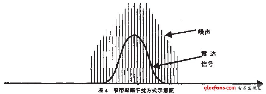
Narrowband tracking jamming is a point noise jamming technology that mainly makes the bandwidth of the narrowband noise signal radiated by the jammer just wide enough to effectively interfere with the radar's operating frequency band and obtain the maximum jamming power spectrum density. This working mode is more likely to burn out the highly sensitive circuits in the radar, making it difficult for the opponent's radar to resume work in a short time. Its working mode is shown in Figure 4.

Figure 4 Schematic diagram of narrowband tracking interference mode
.Circuit implementation for suppressing interference
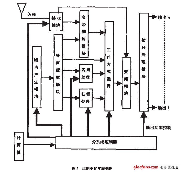
This simulation system is designed with two control modes: RS232 serial port program control and panel keyboard operation. All operation results are displayed on the display on the system panel. In order to ensure signal coherence, the system adopts a separate system of intermediate frequency and microwave sources. The intermediate frequency signal generated by the intermediate frequency part is output, and then modulated to a specific frequency band through frequency conversion processing, and then the corresponding noise suppression signal is obtained through the radio frequency processing module. The system mainly includes six functional modules, and the principle block diagram is shown in Figure 5.

(1) Noise generation module.
This module mainly uses digital technology to modulate the noise source, solving the technical problems of narrow bandwidth and difficult control of noise sources previously achieved with analog methods. It is also more conducive to the programmable control of noises with different bandwidths.
(2) Noise extraction and frequency conversion module.
For different radar operating frequency bands, the noise extraction and frequency conversion module mainly completes the segmented extraction of white noise, and then generates the suppression interference signal of the corresponding frequency band through frequency conversion processing.
(3) Subsystem controller.
The subsystem controller uses Amtd's high-performance single-chip microcomputer A9C51, and the keyboard and display control uses the general programmable I/O interface device 82"/9 produced by Imel. Since it can provide scanning signals, it can replace the microprocessor to complete the control of the keyboard and display, thereby reducing the burden on the host. The circuit uses a 4×6 matrix keyboard to provide users with function switching, output channel switching and interference parameter settings. These parameters mainly include noise bandwidth, flicker frequency, scanning wave frequency, attenuation, etc.
(4) Radio frequency processing module.
The RF processing module mainly performs functions such as power division, RF amplification, and attenuation.
(5) Computer remote control module.
The computer control module mainly realizes the remote program control of the system and is connected to the subsystem control module through the RS232 serial port.
(6) Receiving module.
As an important part of the jamming simulation system, the receiving module is particularly important in the narrowband tracking jamming mode. The quality of the receiving module design will directly affect the performance of the narrowband tracking jamming. This module uses a digital frequency discrimination circuit to overcome the shortcomings of low frequency discrimination accuracy, narrow frequency discrimination bandwidth, and difficulty in program control. However, with the improvement of frequency discrimination accuracy, the response time of the system is relatively delayed. Therefore, high-precision and high-response frequency discrimination circuits are under further research.
Previous article:19 grounding electrode installation standards
Next article:Analysis of a New Current Limit Comparator
- Popular Resources
- Popular amplifiers
- High signal-to-noise ratio MEMS microphone drives artificial intelligence interaction
- Advantages of using a differential-to-single-ended RF amplifier in a transmit signal chain design
- ON Semiconductor CEO Appears at Munich Electronica Show and Launches Treo Platform
- ON Semiconductor Launches Industry-Leading Analog and Mixed-Signal Platform
- Analog Devices ADAQ7767-1 μModule DAQ Solution for Rapid Development of Precision Data Acquisition Systems Now Available at Mouser
- Domestic high-precision, high-speed ADC chips are on the rise
- Microcontrollers that combine Hi-Fi, intelligence and USB multi-channel features – ushering in a new era of digital audio
- Using capacitive PGA, Naxin Micro launches high-precision multi-channel 24/16-bit Δ-Σ ADC
- Fully Differential Amplifier Provides High Voltage, Low Noise Signals for Precision Data Acquisition Signal Chain
- Innolux's intelligent steer-by-wire solution makes cars smarter and safer
- 8051 MCU - Parity Check
- How to efficiently balance the sensitivity of tactile sensing interfaces
- What should I do if the servo motor shakes? What causes the servo motor to shake quickly?
- 【Brushless Motor】Analysis of three-phase BLDC motor and sharing of two popular development boards
- Midea Industrial Technology's subsidiaries Clou Electronics and Hekang New Energy jointly appeared at the Munich Battery Energy Storage Exhibition and Solar Energy Exhibition
- Guoxin Sichen | Application of ferroelectric memory PB85RS2MC in power battery management, with a capacity of 2M
- Analysis of common faults of frequency converter
- In a head-on competition with Qualcomm, what kind of cockpit products has Intel come up with?
- Dalian Rongke's all-vanadium liquid flow battery energy storage equipment industrialization project has entered the sprint stage before production
- Allegro MicroSystems Introduces Advanced Magnetic and Inductive Position Sensing Solutions at Electronica 2024
- Car key in the left hand, liveness detection radar in the right hand, UWB is imperative for cars!
- After a decade of rapid development, domestic CIS has entered the market
- Aegis Dagger Battery + Thor EM-i Super Hybrid, Geely New Energy has thrown out two "king bombs"
- A brief discussion on functional safety - fault, error, and failure
- In the smart car 2.0 cycle, these core industry chains are facing major opportunities!
- The United States and Japan are developing new batteries. CATL faces challenges? How should China's new energy battery industry respond?
- Murata launches high-precision 6-axis inertial sensor for automobiles
- Ford patents pre-charge alarm to help save costs and respond to emergencies
- New real-time microcontroller system from Texas Instruments enables smarter processing in automotive and industrial applications
- 【GD32E231 DIY】Temperature and humidity collection
- Urgent help, AD17 via setting problem?
- Capacitor charging time, MOS gate drive, TL431 reference, op amp followed by ADC sampling, composite tube and complementary push-pull advantages and disadvantages
- Serial communication can also communicate without sharing the same ground. What is the reason?
- C28x Software Tips: How to View Software Examples and Documentation
- CC2500 Migration Instructions
- [DWIN Serial Port Screen] Nucleic Acid Sampling Registration System 2: Prepare Background Image
- The zigbee terminal sets the PAN ID by pressing a button to join the set ID network
- GD32E231 DIY Part 3: LED Smooth Dimming Principle
- Far away, yet close at hand

 Use of EMC filter capacitors


 京公网安备 11010802033920号