This article explains how ground loops form and discusses how to eliminate them using galvanic isolation.
As the name implies, a ground loop is a physical loop in a system's grounding scheme that results from multiple ground paths between circuits. These ground paths can act as a large loop antenna, picking up noise from the environment, which can induce currents in the ground system. The 50/60 Hz magnetic field from AC power is a common source of noise picked up by ground loops. Similarly, for a distributed grounding system, ground voltage noise originating at one location can also cause ground currents to flow in the ground loop. Since ground is low impedance, the noise currents are often quite large. Hundreds of millivolts of noise can cause several amperes of current to flow through the ground loop.
Figure 1 illustrates an example of how ground loop interference can occur in a common data transmission path. Device #1 drives a single-ended signal and device #2 receives the signal. The signal line is grounded to either device. The ground connection can be a shielded coaxial cable, etc. There is another low-impedance path between the grounds of these devices, which flows through the safety ground of the device power supply. The two ground connections form a large loop that picks up noise voltage from the magnetic field of the adjacent interference source. This interference will corrupt the signal received by device #2 and affect the transmission.
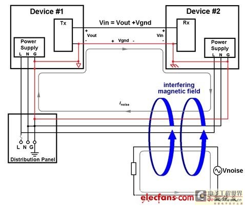
Figure 1: How ground loop interference occurs in a common data transmission path
Designers should be careful to avoid loops by using single-point grounding, but some interfaces require a ground connection between the transceivers. This ground connection must be interrupted while maintaining the flow of information from the transmitter to the receiver. In other words, galvanic isolation is required between the two devices.
One of the possible ways to interrupt the ground loop is to use an optocoupler, as shown in Figure 2.
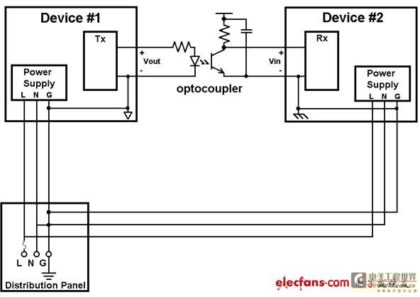
Figure 2: Using an optocoupler to break a ground loop
Device #1 drives the optocoupler's LED, which stimulates current flow in the optocoupler. The ground connection through the cable is eliminated, preventing noise current from flowing between device #1 and device #2, and information is transmitted in the form of light.
As the performance and complexity of the interface increase, this approach has limitations. Optically isolated interfaces can become complex, expensive, and require a lot of board space. The propagation delay of optocouplers is quite large and is only suitable for low-speed signals. When multiple optocouplers are used, the power dissipation in the LEDs and pull-up resistors can become quite high. Digital isolation techniques can be used to break ground loops without affecting interface performance, and the application circuit is simple and requires relatively few components. Digital isolation is a non-optical isolator that uses CMOS interface ICs to transfer information through capacitive or magnetic coupling.
Connecting two AC-powered devices with a USB cable can create a ground loop that disrupts bus communication. USB communication occurs on a pair of bidirectional differential lines (D+ and D- signals in Figure 3). The host device controls the bus and communicates with the peripheral. The direction of the data packet is determined by the USB protocol, not by control signals. The host device provides power and ground connections to the peripheral. This ground connection of the USB cable forms a ground loop with the safety grounds of the host and peripheral, which can cause the ground potential of the peripheral to move relative to the host ground, making communication unreliable (see AN-375, AN-727).
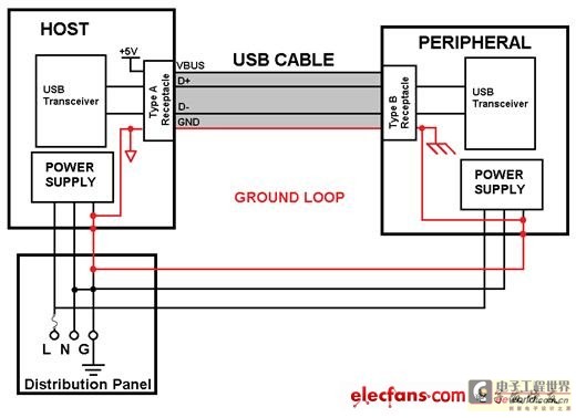
Isolating a USB port to eliminate the cable ground connection is difficult because there are no control signals to indicate whether data is going downstream (peripheral) or upstream (host). Without access to signals inside the Serial Interface Engine (SIE) that controls the bus, the only way to determine the direction of the data is through the bus transaction. The SIE's signals are not available because the SIE is often integrated into the processor.
There are several ways to isolate USB. For example, the challenge of isolating D+ and D- can be avoided by using an external SIE controlled by a serial interface that uses unidirectional signals, such as SPI. SPI is a unidirectional interface, making it easier to isolate.
Figure 4 illustrates this approach. The propagation delay of the optocoupler can severely limit the speed of the isolated SPI, so a four-channel digital isolator is used. The external USB controller sends data from its buffer, which is loaded through the SPI interface. Although the external SIE transmits data at the fastest data rate of the peripheral, the effective data rate of the bus is limited by the controller's ability to keep the SIE buffer full. In this case, the propagation delay of the digital isolator can be a bottleneck. This approach consumes more board space due to the use of an external SIE and may require modifications to the peripheral driver.
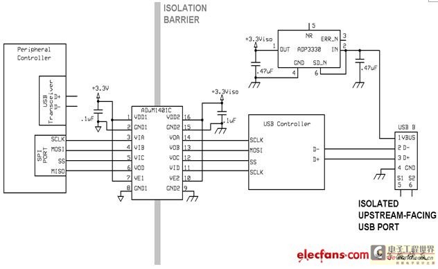
Figure 4: Isolating D+ and D- lines using an external SIE
A simpler approach is to directly isolate the D+ and D- lines using the single-chip ADuM3160 USB isolator, as shown in Figure 5. When using this digital isolator, neither the host nor the peripheral driver needs to be modified, and its internal logic determines the direction of D+ and D- through the USB protocol and disables the driver accordingly. The 2.5kV isolation barrier breaks the ground connection through the USB cable, which would otherwise form a ground loop.
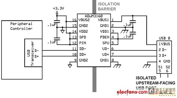
Figure 5: Directly isolating the D+ and D- lines using the ADuM3160 single-chip USB isolator
A simple hardware simulation of a ground loop was designed to illustrate the hazards of ground loops in wired communications and the effectiveness of interrupting ground loops through galvanic isolation. The test setup created a ground loop connected to the USB cable and the power supplies of the USB hub and peripherals, controlled by a laptop. This setup couples the 60 Hz signal from the AC power line to the ground line through a transformer, which is similar to the principle that the magnetic field of the power line creates noise in the ground loop because it relies on the same noise source. The variable series resistor allows the current flowing through the ground loop to be adjustable. The voltage from the hub ground to the peripheral ground is measured, and the current flowing through the ground loop is increased until it breaks communication with the hub. Two different peripherals were used in the test, and both peripherals uniformly lost communication with the hub and laptop when the peripheral ground was more than 1Vrms higher than the hub ground due to the increase in simulated ground loop current. Isolating the hub port with the ADuM3160 USB isolator interrupts the ground connection through the USB cable, preventing the flow of transformer-coupled current, effectively restoring communication between the PC and either peripheral device, demonstrating that digital isolation can be used to prevent ground loops.
In summary, ground loops can be problematic in wired communications. Multiple ground connections between devices form a loop that can pick up interfering noise from nearby AC magnetic fields. Additionally, if there is a ground potential difference (which can be the case with long-distance communications), it can also contribute to ground loop noise currents. Any of these phenomena can cause data errors. The USB interface is one of the interfaces that can suffer from ground loop interference and is not easily isolated by discrete digital isolators. Hardware simulation of ground loops provides a practical example of how ground loops can affect USB interfaces and how the ADuM3160 USB isolator can solve this problem. Ground loops can also be problematic for interfaces other than USB.
Previous article:Why does the output data bit keep changing when there is no input signal to the ADC?
Next article:The principle and method of filtering harmonic interference by active power filter on DC side
Recommended ReadingLatest update time:2024-11-16 21:44
- High signal-to-noise ratio MEMS microphone drives artificial intelligence interaction
- Advantages of using a differential-to-single-ended RF amplifier in a transmit signal chain design
- ON Semiconductor CEO Appears at Munich Electronica Show and Launches Treo Platform
- ON Semiconductor Launches Industry-Leading Analog and Mixed-Signal Platform
- Analog Devices ADAQ7767-1 μModule DAQ Solution for Rapid Development of Precision Data Acquisition Systems Now Available at Mouser
- Domestic high-precision, high-speed ADC chips are on the rise
- Microcontrollers that combine Hi-Fi, intelligence and USB multi-channel features – ushering in a new era of digital audio
- Using capacitive PGA, Naxin Micro launches high-precision multi-channel 24/16-bit Δ-Σ ADC
- Fully Differential Amplifier Provides High Voltage, Low Noise Signals for Precision Data Acquisition Signal Chain
- Innolux's intelligent steer-by-wire solution makes cars smarter and safer
- 8051 MCU - Parity Check
- How to efficiently balance the sensitivity of tactile sensing interfaces
- What should I do if the servo motor shakes? What causes the servo motor to shake quickly?
- 【Brushless Motor】Analysis of three-phase BLDC motor and sharing of two popular development boards
- Midea Industrial Technology's subsidiaries Clou Electronics and Hekang New Energy jointly appeared at the Munich Battery Energy Storage Exhibition and Solar Energy Exhibition
- Guoxin Sichen | Application of ferroelectric memory PB85RS2MC in power battery management, with a capacity of 2M
- Analysis of common faults of frequency converter
- In a head-on competition with Qualcomm, what kind of cockpit products has Intel come up with?
- Dalian Rongke's all-vanadium liquid flow battery energy storage equipment industrialization project has entered the sprint stage before production
- Allegro MicroSystems Introduces Advanced Magnetic and Inductive Position Sensing Solutions at Electronica 2024
- Car key in the left hand, liveness detection radar in the right hand, UWB is imperative for cars!
- After a decade of rapid development, domestic CIS has entered the market
- Aegis Dagger Battery + Thor EM-i Super Hybrid, Geely New Energy has thrown out two "king bombs"
- A brief discussion on functional safety - fault, error, and failure
- In the smart car 2.0 cycle, these core industry chains are facing major opportunities!
- The United States and Japan are developing new batteries. CATL faces challenges? How should China's new energy battery industry respond?
- Murata launches high-precision 6-axis inertial sensor for automobiles
- Ford patents pre-charge alarm to help save costs and respond to emergencies
- New real-time microcontroller system from Texas Instruments enables smarter processing in automotive and industrial applications
- 8K@60HZ/4K@120HZ ultra-high bandwidth output with stable performance
- New uses for old phones (4) - Install PHP in Termux
- Multi-link technology and large spectrum gains will drive Wi-Fi 7
- The pitfalls of I2C
- These words in the PCB design and manufacturing industry!
- Regarding DDR4's winding length, all you need to know is in this book
- EEWORLD University ---- Amplifier Protection Series
- Introduction to calling DSP functions of TMS320F28335
- Running Debian system on K510 (unsuccessful compilation)
- UWB transceiver DW1000 chip internal diagram

 CVPR 2023 Paper Summary: Vision Applications and Systems
 LM741EN


 京公网安备 11010802033920号