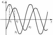
This section discusses the physical meaning of the sinusoidal steady-state solution of the long-line equation. From equation (10-3-6), we know that the voltage
consists of two terms, the first term is
(assuming
), write it as a time function, record it as
, then:
![]()
![]()
![]()

![]() (10-4-1)
(10-4-1)
 is a function of time
t
and distance
x
, which can be written as
. First fix a certain location, let
, then:
![]()
![]()
![]() (10-4-2)
(10-4-2)
In the formula,
is the amplitude of the sine function,
is the initial phase of the sine function. It can be seen
that at
a certain point
is a sinusoidal oscillation of equal amplitude that changes with time. As shown in Figure 10-4-1.
![]()
![]()


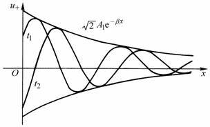
If we fix a certain time
, then:
![]()
![]() (10-4-3)
(10-4-3)
It is
a decaying sinusoidal oscillation with amplitude varying
with distance
x
.
![]()

Figure 10-4-1

Figure 10-4-2
![]() The two
instantaneous
distribution curves along the line are shown in Figure 10-4-2. They are
decaying sine curves with as the envelope.
The two
instantaneous
distribution curves along the line are shown in Figure 10-4-2. They are
decaying sine curves with as the envelope.
![]()

![]()
In summary,
it is a traveling wave that advances in the direction of increasing
x
as time increases
and gradually decays in the advancing direction. This traveling wave that advances from the power supply to the load is called a forward traveling wave.

The propulsion speed of the traveling wave is expressed by the moving speed of the point where the phase remains unchanged, which is called the phase speed and can be calculated by the following formula:
![]() (10-4-4)
(10-4-4)
For overhead transmission lines, the phase velocity is the speed of light in a vacuum, ie
.
![]()
The distance a traveling wave travels in one cycle is called its wavelength
 , so:
, so:
![]() (10-4-5)
(10-4-5)
The second term of
voltage in formula (10-3-6)
is
(assuming
), and the corresponding time function is recorded as
:
![]()
![]()
![]()

![]() (10-4-6)
(10-4-6)
 It is an attenuated wave that propagates along
the direction of decreasing
x
with phase velocity
, that is, an attenuated sine wave that propagates along the line from the terminal to the starting end, which is called a reverse traveling wave.
![]()
Similarly, the current I in formula (10-3-7) can also be decomposed into a direct current wave and a current echo wave, namely:
![]() (10-4-7)
(10-4-7)
Now let's explain the meaning of characteristic impedance. From equations (10-4-6) and (10-4-7), we can see that:
![]() (10-4-8)
(10-4-8)
Characteristic impedance
is the ratio of incident voltage to incident current,
also known as wave impedance.
![]()
![]()
Write the voltage and current as instantaneous function expressions:
 (10-4-9)
 (10-4-10)
In the formula:
.
![]()
The ratio of the reflected voltage (or reflected current) to the incident voltage (or incident current) at any point along the transmission line is called the reflection coefficient N. It can be proved that:
![]() (10-4-11)
(10-4-11)
Where:
is the initial input impedance.
![]()
Another expression for N is:
![]() (10-4-12)
(10-4-12)
On the terminal:
![]() (10-4-13)
(10-4-13)
Where:
is the terminal load impedance.
![]()
Previous article:Principle of light emitting diode
Next article:Sinusoidal Steady-State Analysis of Uniform Transmission Lines
- Popular Resources
- Popular amplifiers
- High signal-to-noise ratio MEMS microphone drives artificial intelligence interaction
- Advantages of using a differential-to-single-ended RF amplifier in a transmit signal chain design
- ON Semiconductor CEO Appears at Munich Electronica Show and Launches Treo Platform
- ON Semiconductor Launches Industry-Leading Analog and Mixed-Signal Platform
- Analog Devices ADAQ7767-1 μModule DAQ Solution for Rapid Development of Precision Data Acquisition Systems Now Available at Mouser
- Domestic high-precision, high-speed ADC chips are on the rise
- Microcontrollers that combine Hi-Fi, intelligence and USB multi-channel features – ushering in a new era of digital audio
- Using capacitive PGA, Naxin Micro launches high-precision multi-channel 24/16-bit Δ-Σ ADC
- Fully Differential Amplifier Provides High Voltage, Low Noise Signals for Precision Data Acquisition Signal Chain
- Innolux's intelligent steer-by-wire solution makes cars smarter and safer
- 8051 MCU - Parity Check
- How to efficiently balance the sensitivity of tactile sensing interfaces
- What should I do if the servo motor shakes? What causes the servo motor to shake quickly?
- 【Brushless Motor】Analysis of three-phase BLDC motor and sharing of two popular development boards
- Midea Industrial Technology's subsidiaries Clou Electronics and Hekang New Energy jointly appeared at the Munich Battery Energy Storage Exhibition and Solar Energy Exhibition
- Guoxin Sichen | Application of ferroelectric memory PB85RS2MC in power battery management, with a capacity of 2M
- Analysis of common faults of frequency converter
- In a head-on competition with Qualcomm, what kind of cockpit products has Intel come up with?
- Dalian Rongke's all-vanadium liquid flow battery energy storage equipment industrialization project has entered the sprint stage before production
- Allegro MicroSystems Introduces Advanced Magnetic and Inductive Position Sensing Solutions at Electronica 2024
- Car key in the left hand, liveness detection radar in the right hand, UWB is imperative for cars!
- After a decade of rapid development, domestic CIS has entered the market
- Aegis Dagger Battery + Thor EM-i Super Hybrid, Geely New Energy has thrown out two "king bombs"
- A brief discussion on functional safety - fault, error, and failure
- In the smart car 2.0 cycle, these core industry chains are facing major opportunities!
- The United States and Japan are developing new batteries. CATL faces challenges? How should China's new energy battery industry respond?
- Murata launches high-precision 6-axis inertial sensor for automobiles
- Ford patents pre-charge alarm to help save costs and respond to emergencies
- New real-time microcontroller system from Texas Instruments enables smarter processing in automotive and industrial applications
- Looking for experts in Helmholtz coil magnetic field
- Do you know about the programmer and emulator of msp430?
- How to use the VGA_SYNC_N signal in the VGA of DE1-SOC?
- ATA-1000 Series Broadband Amplifier & ATA-2000 Series High Voltage Amplifier Series Comparison
- CCS Tips: Remove the prompt when burning DSP/BIOS
- SEED-DEC6416 is available for purchase, second-hand is also acceptable
- Calculation of stack usage in C2000 DSP
- IRLR024 Output Current
- Bidirectional thyristor circuit wiring problem
- "Goodbye 2019, Hello 2020" + The wind and clouds are free and happy

 LF357ID


 京公网安备 11010802033920号