Assembly language (English: assembly language): Any low-level language used in electronic computers, microprocessors, microcontrollers, or other programmable devices. In different devices, assembly language corresponds to different machine language instruction sets. An assembly language is specialized for a certain computer system structure, unlike many high-level languages, which can be portable between different system platforms.
Keil: It is an IDE (integrated development environment) produced by the American Keil Software Company that supports the 8051 series microcontroller architecture.
AT89C51: It is a low-voltage, high-performance CMOS 8-bit microprocessor with 4K-byte FLASH memory (FPEROM—Flash Programmable and Erasable Read Only Memory), commonly known as single-chip microcomputer.
Puzhong development version schematic diagram:

Title: The electronic calculator is based on the 51 development board, using the keyboard as key input and the digital tube as display output to design an electronic calculator. Functional requirements: (1) Realize the addition, subtraction, multiplication and division functions of more than 3 decimal digits; (2) Realize the calculation of positive and negative numbers; (3) Continuous calculation, that is, continue to perform four arithmetic operations on the basis of the previous calculation result.
1. Division of work among group members
Division of labor: The design was mainly completed by me and other team members. I was responsible for the display function of the hardware, the judgment of the buttons, the logic of each module, and the splicing and combination of all modules. My teammates were responsible for the addition, subtraction, multiplication and division algorithms, and the overall framework concept. .
2. Design requirements
Experimental purpose: Design an electronic calculator to realize addition, subtraction, multiplication and division functions of more than 3 decimal digits, and realize positive and negative number operations and continuous operations.
Design requirements: Based on the 51 development board, use the matrix keyboard as key input and the digital tube as display output
"Assembly Language Programming Practice" is an independent practical course offered for assembly language programming courses. It is necessary to consolidate and deepen the understanding of assembly language programming, strengthen students' practical ability and improve students' comprehensive quality. Through a week of study and design, students can master the basic methods of assembly language programming and microcontroller application development, thereby gaining the basic ability to develop microcontroller systems based on assembly language.
(1) Master the assembly instruction system and syntax, and have the ability to design and develop assembly language programming. For complex engineering problems, be able to use assembly language to design and develop corresponding functional modules.
(2) Master the structure and working mechanism of the microcontroller, and be able to develop unit modules that meet the needs of factory applications based on the microcontroller hardware system.
(3) Have the ability to use assembly language design to implement relevant application development based on microcontroller hardware. Able to use a combination of software and hardware methods to conduct research on complex engineering problems in the computer field and design reasonable experimental plans.
3. Design ideas
3.1 Overall framework
flow chart:

Figure 3-1 Flowchart
①Matrix keyboard module
Composition: This module is composed of 16 touch buttons. One end of the buttons in the same row is connected, and one end of the buttons in the same column is also connected.
Main purpose: Complete corresponding operations according to the keys used by the user, that is, input operands and operators.
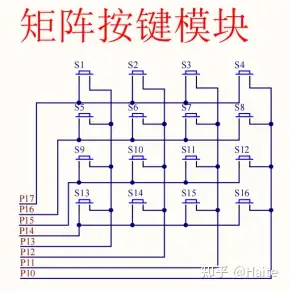
Figure 3-2 Matrix button schematic diagram
In addition, a special note is given on the matrix keyboard layout. This matrix keyboard has a total of 16 keys, 10 of which are numeric input keys, and the other 6 are function keys. Each of them is explained below with a diagram.
Calculator key distribution:
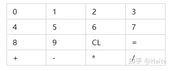
Figure 3-3 Button layout
1.0~9: Numeric keys. When this key is pressed, numbers are entered into the calculator
2.CL: All clear key. After pressing this key, the calculator will clear all information.
3."=": equals sign. After pressing this key, the microcontroller will perform the operation and display the result.
4. "+": addition key. After pressing this key, the microcontroller will save the first operand and record the addition operation.
4. "-": subtraction key. After pressing this key, the microcontroller will save the first operand and record the subtraction operation.
4. "*": multiplication key. After pressing this key, the microcontroller will save the first operand and record the multiplication operation.
4. "/": Division key. After pressing this key, the microcontroller will save the first operand and record the division operation.
②Nigital tube display module
Composition: This module consists of eight seven-segment common cathode digital tubes.

Figure 3-3 Dynamic digital tube schematic diagram
Main purpose: It is used to display the key value pressed on the matrix keyboard and the final calculated result.
③Independent keyboard backspace module (extension module)
Composition: This module consists of an independent keyboard.
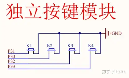
Figure 3-5 Independent button schematic diagram
Main purpose: It is used to roll back the last numeric key pressed by the user and re-enter it.
④Independent keyboard minus module
Composition: This module consists of an independent keyboard.
Main purpose: used to enter negative numbers.
3.3 Program List
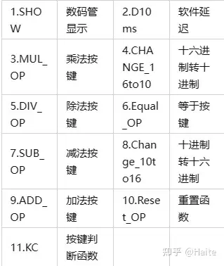
Table 3.1 Program List
4. Function module function design
①Addition:
Point the pointer to the lowest address of the two operands and perform the addition operation. If the result is 10, the result of carry cy=1 is retained, and 0 is stored in the result address. If it is not 10, the original result is stored in the retained result address, and the pointer is incremented. One points to the next operation bit, performs the signed addition operation of the next bit, and loops the process until the four-digit results of the two operands are completed.
②Subtraction:
First point the pointer to the highest bit of the two operands, judge from the highest bit to the lowest bit of the operand, and compare the size of the subtrahend and the minuend. If the subtrahend is greater than the minuend, the negative sign flag is set to 1, then Exchange the operation positions of the subtrahend and the minuend. If the subtrahend is not greater than the minuend, the positions of the two operands are not changed. Then the pointer points back to the highest bit of the operand, and a signed subtraction operation is performed from the highest bit to the lowest bit. , store the result into the target address
flow chart:
①Addition:
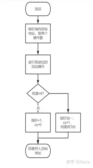
Figure 4-1 Addition flow chart
②Subtraction:
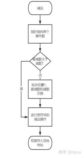
Figure 4-2 Subtraction flow chart
③Multiplication:
The essence of multiplication is that a number n is incremented m times, so it is recorded as n*m. So our idea is to obtain two operands from the microcontroller, the first operand n is incremented by the second operand m times, and use Opcode DA to directly implement decimal multiplication.
④Division (including division remainder expansion):
When performing division, we obtain two operands from the microcontroller and divide between two registers and two registers. Therefore, we need to move to the left 16 times and put two registers in front of the dividend register. An operand is shifted left, and the left shift enters the two registers before the dividend register. After subtracting the divisor from the values in the two registers, if cy is equal to 0, it means that subtraction can be performed. At this time, the dividend and quotient must be shifted left. , the quotient needs to be added by one, and the remainder is placed in these two registers. If cy=1, it means that the subtraction is not enough. At this time, the dividend and the quotient must be shifted to the left, but the quotient should not be added by one, and this cycle is repeated 16 times. Store the quotient in the destination address.
flow chart:
③Multiplication:

Figure 4-3 Multiplication flow chart
④Division:
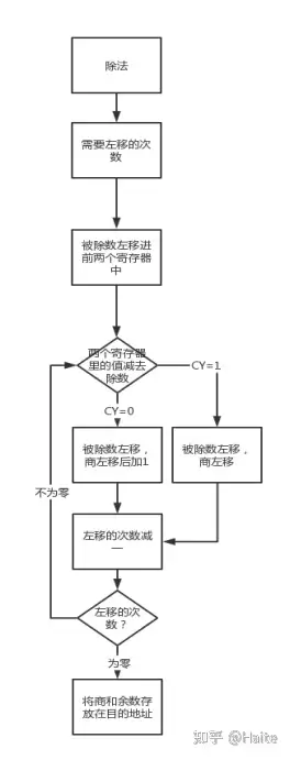
Figure 4-4 Division flow chart
4. Realize the effect
The first four digits of the digital tube are the first operand, and the last four digits of the digital tube are the second operand.
The figure shows the addition operation:
Sum 11+22=33
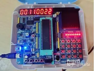
Figure 4-5 Implementation effect diagram 1
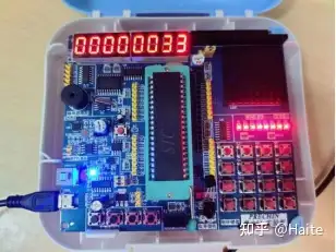
Figure 4-6 Implementation effect diagram 2
When a negative number operation occurs, the first bit of the LED digital tube is the sign bit and displays a negative sign.
The picture shows the subtraction operation:
Find the difference 33-66=-33
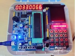
Figure 4-7 Implementation effect diagram 3
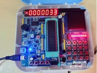
Figure 4-8 Implementation effect diagram 4
When performing continuous operations, the previous operation result located in the last four digits of the digital tube is moved to the first four digits of the digital tube as the first operand, and the last four digits are used for the input of the next operand.
The picture shows the continuous multiplication operation:
Find the product -33*11=-363
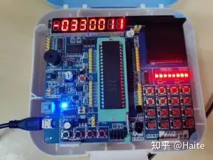
Figure 4-9 Implementation effect diagram 5
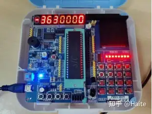
Figure 4-10 Implementation effect diagram 6
When performing division operation, the last four digits of the digital tube display the quotient of the division operation, and the first four digits of the digital tube display the remainder.
The picture shows the continuous division operation:
Find the quotient -363/66=5 Find the remainder -363%66=-33
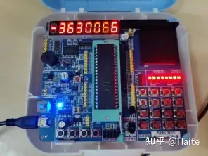
Figure 4-11 Implementation effect diagram 7
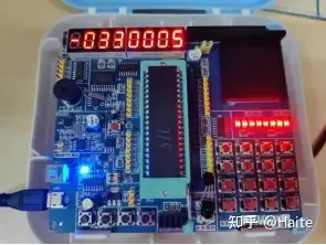
Figure 4-12 Implementation effect diagram 8
5. Summary
① Learn how to convert user input into decimal for calculations, and use decimal for output display.
② Master the four arithmetic operations with more than 3 digits, and use decimal system for addition, subtraction, multiplication and division.
③ Learn how to add test code to the program to find bugs in the program (for example, when judging whether to enter a subroutine, you can change the values 49H~53H in the subroutine so that the digital tube outputs the corresponding result to This determines the location of the bug)
④ Use the essence of the initial learning of addition, subtraction, multiplication and division operations to convert addition, subtraction, multiplication and division operations into addition and subtraction operations, and implement four arithmetic operations with more than three decimal digit operands in assembly language.
Previous article:Based on 51 microcontroller, using interrupts to achieve key counting within 100
Next article:Humidity detection system based on 51 microcontroller
- Naxin Micro and Xinxian jointly launched the NS800RT series of real-time control MCUs
- How to learn embedded systems based on ARM platform
- Summary of jffs2_scan_eraseblock issues
- Application of SPCOMM Control in Serial Communication of Delphi7.0
- Using TComm component to realize serial communication in Delphi environment
- Bar chart code for embedded development practices
- Embedded Development Learning (10)
- Embedded Development Learning (8)
- Embedded Development Learning (6)
 Professor at Beihang University, dedicated to promoting microcontrollers and embedded systems for over 20 years.
- Intel promotes AI with multi-dimensional efforts in technology, application, and ecology
- ChinaJoy Qualcomm Snapdragon Theme Pavilion takes you to experience the new changes in digital entertainment in the 5G era
- Infineon's latest generation IGBT technology platform enables precise control of speed and position
- Two test methods for LED lighting life
- Don't Let Lightning Induced Surges Scare You
- Application of brushless motor controller ML4425/4426
- Easy identification of LED power supply quality
- World's first integrated photovoltaic solar system completed in Israel
- Sliding window mean filter for avr microcontroller AD conversion
- What does call mean in the detailed explanation of ABB robot programming instructions?
- STMicroelectronics discloses its 2027-2028 financial model and path to achieve its 2030 goals
- 2024 China Automotive Charging and Battery Swapping Ecosystem Conference held in Taiyuan
- State-owned enterprises team up to invest in solid-state battery giant
- The evolution of electronic and electrical architecture is accelerating
- The first! National Automotive Chip Quality Inspection Center established
- BYD releases self-developed automotive chip using 4nm process, with a running score of up to 1.15 million
- GEODNET launches GEO-PULSE, a car GPS navigation device
- Should Chinese car companies develop their own high-computing chips?
- Infineon and Siemens combine embedded automotive software platform with microcontrollers to provide the necessary functions for next-generation SDVs
- Continental launches invisible biometric sensor display to monitor passengers' vital signs
- Simulation Research of Parallel Active Power Filter Based on DSP
- Arduino is about to release the Portenta H7 development board
- How to determine the polarity of electrolytic capacitors
- [Zero-knowledge ESP8266 tutorial] Advanced 1 WIFI MESH networking example
- [Industrial Equipment Edge Intelligence Solution] Part 2: Low-power 3-axis accelerometer + 3-axis gyroscope + Bluetooth debugging
- Does ON Semiconductor's device have no AD library?
- Highlight Review丨What hard-core technologies did ADI demonstrate at IMS 2019?
- TOPSwitch?GX series single-chip switching power supply rapid design method
- DMA and interrupt implementation of PCI data acquisition card.pdf
- Negative power supply design


 AUTOSAR MCAL Principles and Practice
 Cortex Microcontroller Software Interface Standard (CMSIS)


 京公网安备 11010802033920号