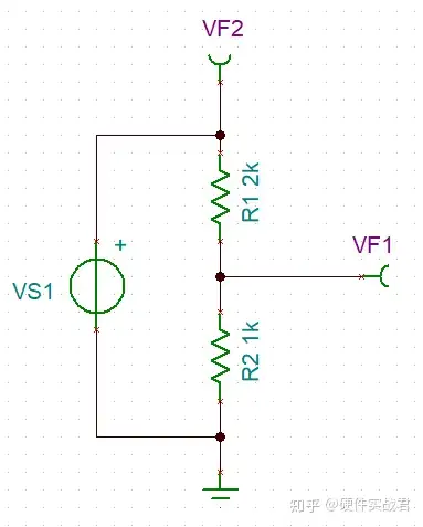
As shown in the figure below, two resistors are used to divide the voltage. The resistance value can be 2:1. After dividing the voltage, 1/3 of the voltage of the signal source is obtained. In this way, the signal varying between 0-10V can be converted into a voltage between 0-3.33V. signals that change between times. As shown in the figure below, it is the most basic resistor voltage dividing sampling principle diagram. I used 2K and 1K resistor dividers.

The simulation waveform is shown in the figure below.

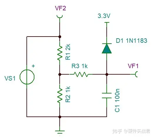
To improve the above figure, use R3 and C1 to form a low-pass filter circuit to filter out high-frequency interference signals during the transmission process. The resistors and capacitors should be close to the ADC pins of the microcontroller during PCB layout. Diode D1 is a clamping diode, which is used to ensure that VF1 can be maintained at a safe voltage when there is a circuit failure (such as R2 being soldered or R2 and R1 resistors being soldered in the wrong position, etc.), or when a peak surge voltage occurs, so as not to damage the microcontroller. . D1 in the circuit should choose a Schottky diode with reduced conduction voltage.

The figure below shows that when R1 and R2 are deliberately soldered to the wrong position, diode D1 starts to work, clamping VF1 at a safe voltage, protecting the microcontroller.

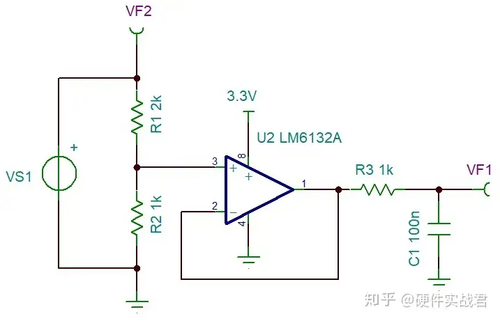
In the above circuit, current will flow through R3 during operation, which affects the sampling accuracy. Continuing to optimize the above circuit, an input and output Rail-to-rail op amp is used to form a voltage follower.

The circuit uses the characteristic that the input impedance of the op amp is infinite under ideal circumstances. It has little impact on the R1 and R2 voltage dividing circuits during signal collection, making the resistor voltage dividing results more accurate.
Careful friends should have noticed that the clamping diode for protection has been removed from the circuit. So, does such a circuit still have the ability to protect the microcontroller when a fault occurs? The answer is yes. For the specific reasons, you can review the input and output rail-to-rail in the op amp parameters.
Previous article:How a microcontroller can elegantly read 0-10V sensor signals (2)
Next article:How should I learn microcontroller? Can it be done quickly?
- Popular Resources
- Popular amplifiers
- Naxin Micro and Xinxian jointly launched the NS800RT series of real-time control MCUs
- How to learn embedded systems based on ARM platform
- Summary of jffs2_scan_eraseblock issues
- Application of SPCOMM Control in Serial Communication of Delphi7.0
- Using TComm component to realize serial communication in Delphi environment
- Bar chart code for embedded development practices
- Embedded Development Learning (10)
- Embedded Development Learning (8)
- Embedded Development Learning (6)
 Professor at Beihang University, dedicated to promoting microcontrollers and embedded systems for over 20 years.
- Intel promotes AI with multi-dimensional efforts in technology, application, and ecology
- ChinaJoy Qualcomm Snapdragon Theme Pavilion takes you to experience the new changes in digital entertainment in the 5G era
- Infineon's latest generation IGBT technology platform enables precise control of speed and position
- Two test methods for LED lighting life
- Don't Let Lightning Induced Surges Scare You
- Application of brushless motor controller ML4425/4426
- Easy identification of LED power supply quality
- World's first integrated photovoltaic solar system completed in Israel
- Sliding window mean filter for avr microcontroller AD conversion
- What does call mean in the detailed explanation of ABB robot programming instructions?
- 2024 China Automotive Charging and Battery Swapping Ecosystem Conference held in Taiyuan
- State-owned enterprises team up to invest in solid-state battery giant
- The evolution of electronic and electrical architecture is accelerating
- The first! National Automotive Chip Quality Inspection Center established
- BYD releases self-developed automotive chip using 4nm process, with a running score of up to 1.15 million
- GEODNET launches GEO-PULSE, a car GPS navigation device
- Should Chinese car companies develop their own high-computing chips?
- Infineon and Siemens combine embedded automotive software platform with microcontrollers to provide the necessary functions for next-generation SDVs
- Continental launches invisible biometric sensor display to monitor passengers' vital signs
- Another technical solution for power-type plug-in hybrid: A brief discussion on Volvo T8 plug-in hybrid technology
- Power Management
- TPS546D24_C23 dynamic voltage regulation
- Sampling Theorem-------------What is the relationship between the detected signal and the ADC sampling rate?
- Showing off the products + CSR development board 10 years ago, when the Bluetooth market was just beginning to develop!
- LIN communication wake-up question
- Parallel Flash
- An introduction to TI's high-efficiency integrated power supply selection and reference designs
- How much does one stm32f103c8t6 chip cost?
- About the problem of the ambient light sensor of the rsl10-sense-gevk board not working well
- Embedded Training Experts

 MSH-840


 京公网安备 11010802033920号