type of data
This is the second part of a series of tutorials on ARM assembly basics, covering data types and registers.

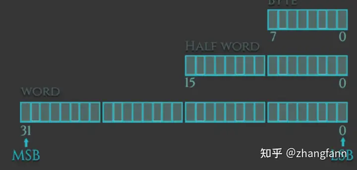
Similar to high-level languages, ARM supports operations on different data types. The data types we can load (or store) can be signed and unsigned words, halfwords, or bytes. The extensions to these data types are. -h or -sh for halfwords, -b or -sb for bytes, and words without extension. The difference between signed and unsigned data types is.
Signed data types can accommodate both positive and negative values and therefore have a smaller range.
Unsigned data types can hold large positive values (including "zero"), but not negative values, so they have a wider range.
Below are some examples of how these data types are used with the Load and Store instructions.

Big and small endian
In memory, there are two basic ways of looking at bytes. Little endian (LE) or big endian (BE). The difference is the order in which each byte of an object is stored in memory. On little-endian machines like Intel x86, the least significant byte is stored at the lowest address (the address closest to zero). On big-endian machines, the most significant byte is stored at the lowest address. The ARM architecture was little-endian until version 3, and since then it has been dual-endian, meaning it has a setting that allows for switchable endianness. For example, in ARMv6, instructions are fixed little endian and data accesses can be little endian or big endian, controlled by bit 9 (E bit) of the Program Status Register (CPSR).

ARM register
The number of registers depends on the ARM version. According to the ARM reference manual, there are 30 general-purpose 32-bit registers except for ARMv6-M and ARMv7-M based processors. The first 16 registers are accessible in user-level mode, and the other registers are available in privileged software execution (except for ARMv6-M and ARMv7-M). In this series of tutorials, we will deal with a register that is accessible in any privileged mode: r0-15. These 16 registers can be divided into two groups: general-purpose registers and special-purpose registers.


The following table shows the relationship between ARM registers and registers in Intel processors.

R0-R12: Can be used to store temporary values, pointers (memory locations), etc. in normal operations. For example, R0 can be used as an accumulator when performing arithmetic operations, or to store the results of previously called functions. R7 becomes very useful when handling system calls as it stores the number of the system call and R11 helps us keep track of boundaries on the stack as frame pointers (to be covered later). Additionally, ARM's function calling convention states that the first four parameters of a function are stored in registers r0-r3.
R13: SP (stack pointer). The stack pointer points to the top of the stack. The stack is an area of memory used for specific function storage and is reclaimed when the function returns. Therefore, the stack pointer is used to allocate space on the stack by subtracting the value we want to allocate (in bytes) from the stack pointer. In other words, if we want to allocate a 32-bit value, we subtract 4 from the stack pointer.
R14: LR (link register). When a function is called, the link register is updated with the memory address referencing the next instruction initiated by the function. Doing this allows the program to return to the "parent" function that started the "child" function after the "child" function has completed.
R15: PC (program counter). The program counter is automatically incremented based on the size of instructions executed. This size is always 4 bytes in ARM state and 2 bytes in THUMB mode. When a branch instruction is executed, the PC saves the target address. During execution, the PC stores the address of the current instruction plus 8 (two ARM instructions) in the ARM state, and stores the address of the current instruction plus 4 (two Thumb instructions) in the Thumb (v1) state. This is different from x86, where the PC always points to the next instruction to be executed.
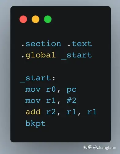
Let's see how the PC behaves in the debugger. We use the following program to store the address of the PC into r0 and include two random instructions. Let's see what happens.

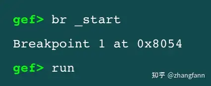
In gdb we set a breakpoint at _start

The following is the result of the operation:

We can see that PC holds the address (0x8054) of the next instruction that will be executed (mov r0, pc). Now let's execute the next instruction, after which R0 should hold the address of PC (0x8054), right?

...Is it right? wrong. Look at the address in R0. While we expected R0 to contain the PC value we read previously (0x8054), it instead contains a value two instructions ahead of the PC value we read previously (0x805c). You can see from this example that when we read the PC directly, it follows the definition that the PC points to the next instruction; but when debugging, the PC points to two instructions before the current PC value (0x8054 + 8 = 0x805C). This is because older ARM processors always fetch two instructions before the currently executing instruction. The reason ARM retains this definition is to ensure compatibility with earlier processors.
Current program status register
When you use gdb to debug an ARM binary, you will see something called Flags.

Register $cpsr shows the value of the current program status register (CPSR). Below it you can see Flagsthumb, fast, interrupt, overflow, carry, zero, and negative. These flags represent certain bits in the CPSR register and are set based on the value of the CPSR, turning bold when activated. The N, Z, C, and V bits are the same as the SF, ZF, CF, and OF bits in the EFLAG register on x86. These bits are used to support assembly-level conditionals and conditional execution of loops. We'll cover using conditional code in Part 6, "Conditional Execution and Branching."

The figure above shows the layout of a 32-bit register (CPSR), with the left (<-) being the most significant bits and the right (->) being the smallest bits. Each unit (except the GE and M parts and the blank part) is one bit in size. These one-bit portions define various properties of the current state of the program.

Let us assume that we use CMP instruction to compare numbers 1 and 2. The result is "negative" because 1-2=-1. When we compare two equal numbers, say 2 versus 2, the Z (zero) flag is set because 2-2=0. Remember that the registers used by the CMP instruction are not modified, only the CPSR is modified based on the results of comparing these registers with each other.
This is the case in GDB (with GEF installed). In this example, we compare registers r1 and r0, where r1=4 and r0=2. This is the situation of the flag after executing the cmp r1, r0 operation.

The carry flag is set because we used cmp r1, r0 to compare 4 and 2 (4-2). Conversely, if we use cmp r0, r1 to compare a smaller number (2) with a larger number (4), the negative flag (N) is set.
Here is an excerpt from the ARM Information Center:
APSR contains the following ALU status flags.
N - Set when the result of the operation is negative.
Z - Set when the result of the operation is zero.
C - Set when the result of the operation is a Carry.
V--Set when the operation causes overflow.
carry is set when:
If the result of addition is greater than or equal to 2^32
If the result of subtraction is positive or zero
As a result of an inline shift operation in a move or logic instruction.
If the result of addition, subtraction, or comparison is greater than or equal to 2^31, or less than 2^31, an overflow occurs.
This article is the second part of the ARM assembly tutorial series. It introduces the basic data types of arm and basic register related knowledge.
Previous article:ARM assembly tutorial (3): ARM instruction set
Next article:ARM Assembly Tutorial (1): Introduction to ARM Assembly
Recommended ReadingLatest update time:2024-11-16 16:03


 Professor at Beihang University, dedicated to promoting microcontrollers and embedded systems for over 20 years.
- Innolux's intelligent steer-by-wire solution makes cars smarter and safer
- 8051 MCU - Parity Check
- How to efficiently balance the sensitivity of tactile sensing interfaces
- What should I do if the servo motor shakes? What causes the servo motor to shake quickly?
- 【Brushless Motor】Analysis of three-phase BLDC motor and sharing of two popular development boards
- Midea Industrial Technology's subsidiaries Clou Electronics and Hekang New Energy jointly appeared at the Munich Battery Energy Storage Exhibition and Solar Energy Exhibition
- Guoxin Sichen | Application of ferroelectric memory PB85RS2MC in power battery management, with a capacity of 2M
- Analysis of common faults of frequency converter
- In a head-on competition with Qualcomm, what kind of cockpit products has Intel come up with?
- Dalian Rongke's all-vanadium liquid flow battery energy storage equipment industrialization project has entered the sprint stage before production
- Allegro MicroSystems Introduces Advanced Magnetic and Inductive Position Sensing Solutions at Electronica 2024
- Car key in the left hand, liveness detection radar in the right hand, UWB is imperative for cars!
- After a decade of rapid development, domestic CIS has entered the market
- Aegis Dagger Battery + Thor EM-i Super Hybrid, Geely New Energy has thrown out two "king bombs"
- A brief discussion on functional safety - fault, error, and failure
- In the smart car 2.0 cycle, these core industry chains are facing major opportunities!
- The United States and Japan are developing new batteries. CATL faces challenges? How should China's new energy battery industry respond?
- Murata launches high-precision 6-axis inertial sensor for automobiles
- Ford patents pre-charge alarm to help save costs and respond to emergencies
- New real-time microcontroller system from Texas Instruments enables smarter processing in automotive and industrial applications
- Embedded Learning丨4412 Development Board-uboot Source Code-Assembly-Source Code Analysis (I)
- Using the I2C Bus
- 【Qinheng RISC-V core CH582】Learning material collection
- CCS cannot connect to F280049C Launchpad
- What topics do electronic engineers like?
- Chips are also being counterfeited? How to develop a keen eye and identify "real and fake chips" in the arena!
- I have some hesitations about job hopping, I hope you can give me some advice
- Tips for you: How to design an excellent 5G small base station
- Essential knowledge about gas detectors
- How to Optimize DSP Power Budget

 usb_host_device_code
 Multithreaded computing in embedded real-time operating systems - based on ThreadX and ARM


 京公网安备 11010802033920号