The application of PWM can be said to be very wide, controlling motor speed, light brightness, communication modulation and many other fields.
My friends have asked me a lot about PWM, and I have been using PWM recently. Here I will share some information about PWM.
What is PWM?
PWM: Pulse Width Modulation, pulse width modulation.
There are many explanations on the Internet. Through the picture below, you can intuitively understand PWM, which is actually a pulse signal composed of high and low levels.

By changing the frequency (pulse period) and duty cycle, it can be applied in many situations.

Common PWM output methods
From the above description, PWM is an IO port that outputs high and low levels at different time periods.
1. In the novice (rookie) level while loop, blocking delay controls the high and low output of the IO port:
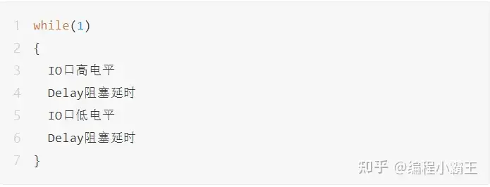
Blocking delay can be: software simulation delay, timer blocking delay, etc.
2. In the entry (junior) level while loop, non-blocking delay controls the high and low output of the IO port:
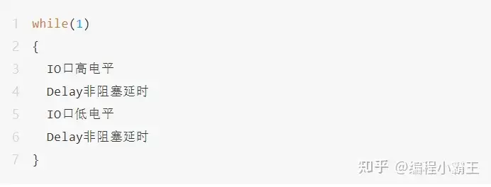
Non-blocking delays can be: timer identification detection, RTOS (system) delays, etc.
3. Familiar with (intermediate) level timer interrupt control IO high and low level output:
Timer interrupt configuration——>Start timer——>Respond to interrupt and control IO high and low levels...
4. Proficient (intermediate+) level
Timer PWM hardware control output:
Configure the IO corresponding to PWM and timer PWM output——> Start PWM automatic output...
Comparison:
Among the above PWM output methods, the first three will cause the CPU to interfere with the PWM output, which means it will occupy CPU resources. Especially the first two methods, not only occupy the CPU, but also have a relatively large error.
Using the third interrupt method, if the frequency is relatively high, the CPU consumption will be serious. This situation is suitable for microcontrollers without hardware PWM output.
The fourth type is that the microcontroller has its own hardware PWM output function. It only needs simple configuration to automatically output PWM waveforms without CPU intervention.
Hardware output PWM example
Here we take the familiar STM32F1 as an example: I will briefly share with you the hardware timer output PWM waveform.
PWM timer related macro definitions:

PWM configuration:


PWM output function interface:

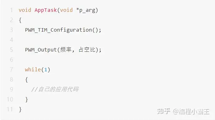
Initialize the configuration, call the function interface, and directly output the PWM waveform:
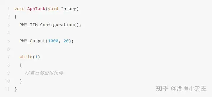
Output PWM waveform:
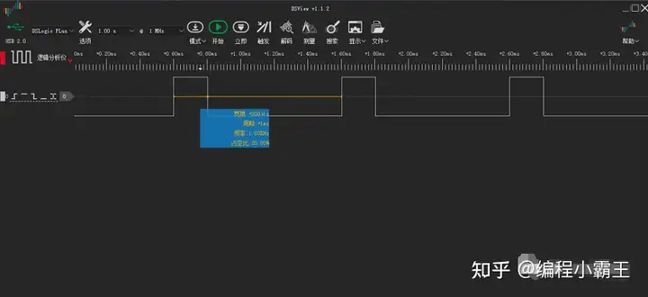
illustrate:
This example uses the STM32 standard peripheral library. If you want to understand the principles in depth, it is recommended to use the standard peripheral library.
Of course, if you want to use the PWM function quickly without understanding its principles, you can directly use the STM32CubeMX configuration to generate code:

Configuration considerations
If you want to control it more accurately and better meet the needs of the application layer, you need to understand the principles step by step.
Let’s talk about some common questions below.
1. Pin mapping
If the pins you use need to be mapped, you need to configure the corresponding parameters.
For example: STM32F1 uses PB11 (need to check the data sheet):

The corresponding "mapping" code needs to be added:

2. Frequency and duty cycle accuracy
If a 32-bit timer is used, the frequency range is wider and the accuracy can be higher. For example: frequency: 0.01Hz, duty cycle 0.01%, etc.
If it is 16 bits, none of the parameters can exceed 16 bits (65535):

You can configure it according to your own situation, such as PWM (timer) counting clock, frequency division value, etc.
For actual application code, it is recommended to add judgment on each parameter to prevent crossing the boundary (here, for the convenience of understanding, it is written relatively simply).
3. More STM32 have hardware PWM output function, but different series may have slightly different configurations. Simply refer to the official routines and manuals.
Nowadays, most microcontrollers have their own hardware PWM output function. The advantage of the hardware is that it does not require CPU intervention. If not, you can try the timer interrupt method mentioned above.
Previous article:How to learn microcontroller data communication? This tool should be used well: serial communication
Next article:The microcontroller firmware is cracked
Recommended ReadingLatest update time:2024-11-23 11:07


- Popular Resources
- Popular amplifiers
-
 西门子S7-12001500 PLC SCL语言编程从入门到精通 (北岛李工)
 -
 Small AC Servo Motor Control Circuit Design (by Masaru Ishijima; translated by Xue Liang and Zhu Jianjun, by Masaru Ishijima, Xue Liang, and Zhu Jianjun)
 -
 Intelligent Control Technology of Permanent Magnet Synchronous Motor (Written by Wang Jun)
 -
 100 Examples of Microcontroller C Language Applications (with CD-ROM, 3rd Edition) (Wang Huiliang, Wang Dongfeng, Dong Guanqiang)
- Naxin Micro and Xinxian jointly launched the NS800RT series of real-time control MCUs
- How to learn embedded systems based on ARM platform
- Summary of jffs2_scan_eraseblock issues
- Application of SPCOMM Control in Serial Communication of Delphi7.0
- Using TComm component to realize serial communication in Delphi environment
- Bar chart code for embedded development practices
- Embedded Development Learning (10)
- Embedded Development Learning (8)
- Embedded Development Learning (6)
 Professor at Beihang University, dedicated to promoting microcontrollers and embedded systems for over 20 years.
- Intel promotes AI with multi-dimensional efforts in technology, application, and ecology
- ChinaJoy Qualcomm Snapdragon Theme Pavilion takes you to experience the new changes in digital entertainment in the 5G era
- Infineon's latest generation IGBT technology platform enables precise control of speed and position
- Two test methods for LED lighting life
- Don't Let Lightning Induced Surges Scare You
- Application of brushless motor controller ML4425/4426
- Easy identification of LED power supply quality
- World's first integrated photovoltaic solar system completed in Israel
- Sliding window mean filter for avr microcontroller AD conversion
- What does call mean in the detailed explanation of ABB robot programming instructions?
- STMicroelectronics discloses its 2027-2028 financial model and path to achieve its 2030 goals
- 2024 China Automotive Charging and Battery Swapping Ecosystem Conference held in Taiyuan
- State-owned enterprises team up to invest in solid-state battery giant
- The evolution of electronic and electrical architecture is accelerating
- The first! National Automotive Chip Quality Inspection Center established
- BYD releases self-developed automotive chip using 4nm process, with a running score of up to 1.15 million
- GEODNET launches GEO-PULSE, a car GPS navigation device
- Should Chinese car companies develop their own high-computing chips?
- Infineon and Siemens combine embedded automotive software platform with microcontrollers to provide the necessary functions for next-generation SDVs
- Continental launches invisible biometric sensor display to monitor passengers' vital signs
- The Maximum Stack Usage in the compiled .htm file is 0 bytes
- [National Technology N32 Bluetooth chip development package] --N32WB452 series
- Regarding the use of UCC27531, I just want to ask a small question
- XC3S200A chip loading problem
- Design and implementation of embedded Bluetooth PSTN voice access point
- AD strange line. Can't delete it no matter what, please help
- Discounted boards are reduced by 100 yuan! Components are available as low as 0 yuan!
- MSP430G2553 clock external crystal configuration instructions
- Difficulty in UHF reader design - anti-collision
- How to use MSP430 hardware I2C - Taking BH1710 and AT24C02 as examples

 西门子S7-12001500 PLC SCL语言编程从入门到精通 (北岛李工)


 京公网安备 11010802033920号