When I was in college, I studied STM8 microcontrollers for one semester. I put a lot of effort into it. I used a textbook from a teacher I admired very much, which was taught in assembly language. However, I admired it very much. Now I think about it, some basic things in this book are not very clear. For example, in the first chapter, the implementation principle of microcontrollers was explained by 51 microcontrollers, and the code of 51 microcontrollers was also used. But this book is about STM8, okay? I have to say that the 51 was used. It is obvious that the book was published in a hurry. There are also some typos in the book, which is a bit strange for someone like me with obsessive-compulsive disorder. Of course, the good thing is that there are many practical engineering things in it, and it also talks about examples of using STM8 assembly to implement multi-tasking, and digital filtering and other things that seemed very interesting to me at the time. I still admire him (Pan Yongxiong) very much. This is the truth. I have read this book many times and I have been reluctant to donate it. Other circuits, analog electronics, and digital electronics have all been donated to others.
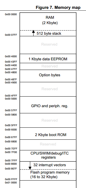
Okay, let's get to the point. Before talking about the boot process of STM8 microcontroller, we must first have a basic understanding of STM8 memory map, which can be found in the STM8 data sheet. The following is a screenshot (of course, this is the memory map of one series of STM8, and others may be different): 
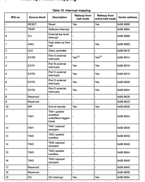
You can see a storage area called "2 Kbyte boot Rom", and the reset vector of hardware reset (from shutdown to startup) is in this area. This is very special because there is a storage area called "32 interrupt vectors" below, and all other interrupt vectors (see the table below) are in this area, only the hardware reset vector is not. 
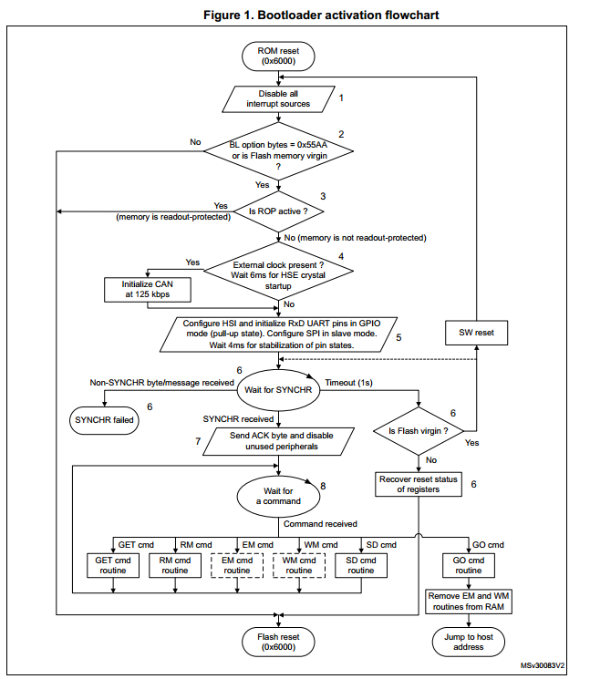
So after the hardware reset, that is, after the STM8 is turned off and on, the first code executed is the code on the boot Rom. The code on the boot Rom is called bootloader. The main function of the bootloader is to burn the microcontroller program into the microcontroller through the integrated peripherals (UART, SPI, CAN) of the microcontroller without using ST-Link. However, this can only be burned when the microcontroller is burned for the first time or the BL and NBL bytes in the Option bytes (this is also in the storage mapping diagram) are set to 55 and AA respectively and the read protection of the memory is not enabled. If the conditions are not met, you can use ST-Link to connect the microcontroller and set the Option bytes in STVP to meet them. The specific flow chart after starting from the boot Rom can be seen in the figure below (the figure comes from the official UM0560), or you can read the text directly. 
After meeting the conditions mentioned above, STM8 will detect whether there is a synchronization signal from the host (usually the computer end). If there is a synchronization signal, STM8 will hand over control to the host, and the host can download the program to STM8 (after downloading, the host specifies the address where the program starts to execute). If the STM8 does not detect the synchronization signal of the host, it will wait for 1 second and then time out. After the timeout, it will determine whether the microcontroller has not been programmed. If so, it will return to the hardware reset state and repeat the process from the hardware reset. If the program has been programmed before, find the entry of the reset vector in "32 interrupt vectors", enter the address pointed by the vector (usually what we call the main function) to start executing the program.
What if the bootloader does not meet the conditions for programming when it starts executing? It also finds the entry of the reset vector in "32 interrupt vectors", enters the address pointed by the vector to start executing the program.
The above is the startup process of the STM8 microcontroller.
Previous article:Implementing absolute address jump in STM8 FOR IAR
Next article:STM8 EEPROM unlocking is repeatable
Recommended ReadingLatest update time:2024-11-16 13:25

![[MCU framework][bsp layer][AT32F415][bsp_pwm] PWM configuration and use](https://6.eewimg.cn/news/statics/images/loading.gif)


- Popular Resources
- Popular amplifiers
-
 Wireless Sensor Network Technology and Applications (Edited by Mou Si, Yin Hong, and Su Xing)
 -
 Modern Electronic Technology Training Course (Edited by Yao Youfeng)
 -
 Modern arc welding power supply and its control
 -
 Small AC Servo Motor Control Circuit Design (by Masaru Ishijima; translated by Xue Liang and Zhu Jianjun, by Masaru Ishijima, Xue Liang, and Zhu Jianjun)
 Professor at Beihang University, dedicated to promoting microcontrollers and embedded systems for over 20 years.
- Innolux's intelligent steer-by-wire solution makes cars smarter and safer
- 8051 MCU - Parity Check
- How to efficiently balance the sensitivity of tactile sensing interfaces
- What should I do if the servo motor shakes? What causes the servo motor to shake quickly?
- 【Brushless Motor】Analysis of three-phase BLDC motor and sharing of two popular development boards
- Midea Industrial Technology's subsidiaries Clou Electronics and Hekang New Energy jointly appeared at the Munich Battery Energy Storage Exhibition and Solar Energy Exhibition
- Guoxin Sichen | Application of ferroelectric memory PB85RS2MC in power battery management, with a capacity of 2M
- Analysis of common faults of frequency converter
- In a head-on competition with Qualcomm, what kind of cockpit products has Intel come up with?
- Dalian Rongke's all-vanadium liquid flow battery energy storage equipment industrialization project has entered the sprint stage before production
- Allegro MicroSystems Introduces Advanced Magnetic and Inductive Position Sensing Solutions at Electronica 2024
- Car key in the left hand, liveness detection radar in the right hand, UWB is imperative for cars!
- After a decade of rapid development, domestic CIS has entered the market
- Aegis Dagger Battery + Thor EM-i Super Hybrid, Geely New Energy has thrown out two "king bombs"
- A brief discussion on functional safety - fault, error, and failure
- In the smart car 2.0 cycle, these core industry chains are facing major opportunities!
- The United States and Japan are developing new batteries. CATL faces challenges? How should China's new energy battery industry respond?
- Murata launches high-precision 6-axis inertial sensor for automobiles
- Ford patents pre-charge alarm to help save costs and respond to emergencies
- New real-time microcontroller system from Texas Instruments enables smarter processing in automotive and industrial applications
- Fudan Micro FM33LC046N Review Summary
- TMS320C55x Assembly Language Programming
- Does the POR of the 430 microcontroller need to be reset if the voltage is not enough?
- Tektronix 618 promotion has started! The lowest price of the year!
- Request a cadencePCB file
- MSP-FET430UIF Win8 Driver
- National College Student Electronic Design Competition TI Processor Board Application Details
- Finally I've waited for you, all the terminal R&D and testing data has been collected!
- Application of Lock-in Amplifier in TDLAS Technology
- Addressing the challenges of diverse multi-standard wireless communication devices in the connected home


 Wireless Sensor Network Technology and Applications (Edited by Mou Si, Yin Hong, and Su Xing)


 京公网安备 11010802033920号