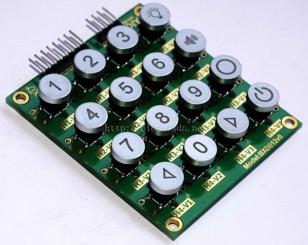
1. What is a matrix keyboard?
A matrix keyboard is a keyboard group with a matrix-like layout used in the external devices of a single-chip microcomputer. Since more external inputs are needed in circuit design, controlling a single key would waste a lot of IO resources, so a matrix keyboard was created. Commonly used matrix keyboards are 4*4 and 8*8, of which 4*4 is the most commonly used.
I searched two pictures online for you to see.


As you can see from the picture above, 4*4 keyboards are still used in many places^_^
2. The principle of matrix keyboard
Matrix keyboard is also called determinant keyboard, which is a keyboard composed of 4 I/O lines as row lines and 4 I/O lines as column lines.
A key is set at each intersection of row lines and column lines. In this way, the number of keys in the keyboard is 4×4.
This determinant keyboard structure can effectively improve the utilization rate of I/O ports in the single-chip microcomputer system. Since the single-chip microcomputer IO port
has the function of line AND, when any key is pressed, a line in the row and column is line ANDed, and
the coordinates of the key can be obtained through calculation to determine the key value.
The principle is the same as the determinant of a matrix series.

3. Driving circuit diagram
The key matrix built with a 4*4 matrix is relatively simple. Some people also add diode protection and pull-up resistors to ensure the stability of the circuit, but generally, circuits with low requirements do not need to add them. The circuit set up below can be used.

4. Software Programming
According to the principle of 4*4 keyboard, the software design procedure is as follows:
//************************************************ ***
//Function function:
//MCU drives 4*4 keyboard, reads keyboard value and uses digital tube static
//Display the key value. If there is no digital tube, you can also use 8421 code to display the LED light.
// Reading principle: First, let the microcontroller port output 11110000 to read once, then
//Let the microcontroller output 00001111 and read it once, add the two values together, and finally
//Get a value with 0 in high and low bits to determine the key value.
//such as 11101110
//************************************************ ***
#include
#define uchar unsigned char
#define uint unsigned int
unsigned char code smg_d[]={0x3f,0x06,0x5b,0x4f,0x66,0x6d,0x7d,0x07,0x7f,0x6f,0x77,0x7c,0x39,0x5e,0x79,0x71};
//************************************************
//Delay function, at 12MHz crystal frequency
//About 50us delay
//************************************************
void delay_50us(uint t)
{
uchar j;
for(;t>0;t--)
for(j=19;j>0;j--);
}
void main()
{
uchar key_l,key_h;
uchar key;
while(1)
{
P1=0xf0;
key_l=P1; //Read the value of P1 port
key_l=key_l&0xf0; //Set the lower 4 bits to 0
if(key_l!=0xf0) // Check if a key is pressed
{
delay_50us(100);
if(key_l!=0xf0)
{ //If a key is pressed, switch the high and low 4 bits to determine the key value
key_l=P1&0xf0; //11100000 Get the first key value
key_l=key_l|0x0f;//11101111
P1=key_l; //Read it again in reverse, because the time when the key is pressed by hand is short,
key_h=P1; //For the microcontroller, it is long enough, so the value can be read twice in both directions
key_h=key_h&0x0f;//00001110
key_l=key_l&0xf0;//11100000
key=key_h+key_l; //11101110
}
}
switch (key)
{
case 0xee:P2=smg_d[0];break;
case 0xde:P2=smg_d[1];break;
case 0xbe:P2=smg_d[2];break;
case 0x7e:P2=smg_d[3];break;
case 0xed:P2=smg_d[4];break;
case 0xdd:P2=smg_d[5];break;
case 0xbd:P2=smg_d[6];break;
case 0x7d:P2=smg_d[7];break;
case 0xeb:P2=smg_d[8];break;
case 0xdb:P2=smg_d[9];break;
case 0xbb:P2=smg_d[10];break;
case 0x7b:P2=smg_d[11];break;
case 0xe7:P2=smg_d[12];break;
case 0xd7:P2=smg_d[13];break;
case 0xb7:P2=smg_d[14];break;
case 0x77:P2=smg_d[15];break;
}
}
}
Previous article:Detailed explanation of matrix keyboard scanning principle - single chip microcomputer
Next article:msp430 PWM period calculation
- Popular Resources
- Popular amplifiers
 Professor at Beihang University, dedicated to promoting microcontrollers and embedded systems for over 20 years.
- LED chemical incompatibility test to see which chemicals LEDs can be used with
- Application of ARM9 hardware coprocessor on WinCE embedded motherboard
- What are the key points for selecting rotor flowmeter?
- LM317 high power charger circuit
- A brief analysis of Embest's application and development of embedded medical devices
- Single-phase RC protection circuit
- stm32 PVD programmable voltage monitor
- Introduction and measurement of edge trigger and level trigger of 51 single chip microcomputer
- Improved design of Linux system software shell protection technology
- What to do if the ABB robot protection device stops
- Allegro MicroSystems Introduces Advanced Magnetic and Inductive Position Sensing Solutions at Electronica 2024
- Car key in the left hand, liveness detection radar in the right hand, UWB is imperative for cars!
- After a decade of rapid development, domestic CIS has entered the market
- Aegis Dagger Battery + Thor EM-i Super Hybrid, Geely New Energy has thrown out two "king bombs"
- A brief discussion on functional safety - fault, error, and failure
- In the smart car 2.0 cycle, these core industry chains are facing major opportunities!
- The United States and Japan are developing new batteries. CATL faces challenges? How should China's new energy battery industry respond?
- Murata launches high-precision 6-axis inertial sensor for automobiles
- Ford patents pre-charge alarm to help save costs and respond to emergencies
- New real-time microcontroller system from Texas Instruments enables smarter processing in automotive and industrial applications
- [Lazy self-care fish tank control system] APP control pins in non-RTE mode of KEIL environment
- POE power supply problem
- Writing Verilog Code for AD Sampling FPGA Program
- capacitance
- Can 1.5V rechargeable lithium batteries really replace traditional dry batteries?
- The basic principles and methods of SRIO error handling
- #idlemarket# Puyuan programmable linear power supply + NETGEAR Gigabit intelligent network management switch
- Insurance and salary issues
- ANT useful information sharing
- EEWorld Forum Spring Festival Holiday Duty Schedule

 TC52N3829ECTRT


 京公网安备 11010802033920号