1 Introduction
STSW-STM32116 is a USART import IAP sample program for STM32F0 based on the standard library on ST official website. Download link: http://www.stmcu.org/document/detail/index/id-213120
The project was originally designed for STM32F051. This article will introduce how to migrate to STM32F070 and deal with the problems encountered during the migration process one by one.
2 KEIL transplantation
IAP programs are generally divided into two, one is IAP and the other is APP. IAP is stored at the starting position of 0x8000000 of the built-in FLASH, while APP is stored at a certain distance from this position. This distance must be greater than or equal to the space occupied by IAP itself. In this example, it is 0x8003000.
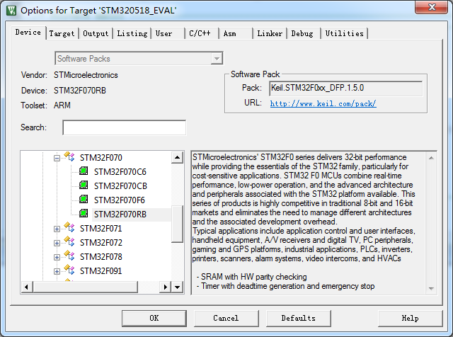
After downloading the resources, open the binary_template project under STM32F0xx_AN4065_FW_V1.0.0\Project\STM32F0xx_IAP\. This is the APP project. First, open it with KEIL and change the device to STM32F070.
And compile, it turns out that the original formula cannot be compiled, with the following error message:
linking...
.\STM320518_EVAL\STM320518_EVAL.axf: Error: L6971E: system_stm32f0xx.o(.data) type RW incompatible with main.o(.ARM.__AT_0x20000000) type ZI in er RW_IRAM1.
Not enough information to list image symbols.
Finished: 1 information, 0 warning and 1 error messages.
".\STM320518_EVAL\STM320518_EVAL.axf" - 1 Error(s), 0 Warning(s).
Target not created.
Build Time Elapsed: 00:00:08
Judging from the literal meaning, the RW data in the data segment (.data) of the target file system_stm32f0xx.o generated by compiling the system_stm32f0xx.c file conflicts with the data in main.o at address 0x20000000.
Looking at the code carefully, I found this paragraph before the main function:
#if (defined ( __CC_ARM ))
__IO uint32_t VectorTable[48] __attribute__((at(0x20000000)));
#elif (defined (__ICCARM__))
#pragma location = 0x20000000
__no_init __IO uint32_t VectorTable[48];
#elif defined ( __GNUC__ )
__IO uint32_t VectorTable[48] __attribute__((section(".RAMVectorTable")));
#elif defined ( __TASKING__ )
__IO uint32_t VectorTable[48] __at(0x20000000);
#endif
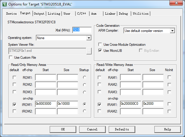
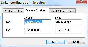
It can be seen that the code is to force the interrupt vector table VectorTable to be defined at memory 0x20000000, but this address conflicts with the global variable position defined in system_stm32f0xx.c. Therefore, it needs to be modified to avoid the conflict. The address of the interrupt vector is fixed, but the addresses of other global variables can be moved accordingly, and the burning location of the APP is 0x8003000, as shown below:
Compile again and the error should go away.
In addition, you need to modify the first few lines of code in the main function:
int main(void)
{
uint32_t i = 0;
/*!< At this stage the microcontroller clock setting is already configured,
this is done through SystemInit() function which is called from startup
file (startup_stm32f0xx.s) before to branch to application main.
To reconfigure the default setting of SystemInit() function, refer to
system_stm32f0xx.c file
*/
/* Relocate by software the vector table to the internal SRAM at 0x20000000 ***/
/* Copy the vector table from the Flash (mapped at the base of the application
load address 0x08003000) to the base address of the SRAM at 0x20000000. */
for(i = 0; i < 48; i++)
{
VectorTable[i] = *(__IO uint32_t*)(APPLICATION_ADDRESS + (i<<2));
}
/* Enable the SYSCFG peripheral clock*/
//RCC_APB2PeriphResetCmd(RCC_APB2Periph_SYSCFG, ENABLE);
RCC_APB2PeriphClockCmd(RCC_APB2Periph_SYSCFG, ENABLE); //Need to be modified like this
/* Remap SRAM at 0x00000000 */
SYSCFG_MemoryRemapConfig(SYSCFG_MemoryRemap_SRAM);
/...
}
Open the corresponding map file, which contains the following content:
GPIO_PIN 0x08003470 Data 8 stm320518_eval.o(.constdata)
GPIO_CLK 0x08003478 Data 16 stm320518_eval.o(.constdata)
BUTTON_PIN 0x08003488 Data 14 stm320518_eval.o(.constdata)
BUTTON_CLK 0x08003498 Data 28 stm320518_eval.o(.constdata)
BUTTON_EXTI_LINE 0x080034b4 Data 14 stm320518_eval.o(.constdata)
BUTTON_PORT_SOURCE 0x080034c2 Data 14 stm320518_eval.o(.constdata)
BUTTON_PIN_SOURCE 0x080034d0 Data 14 stm320518_eval.o(.constdata)
BUTTON_IRQn 0x080034de Data 14 stm320518_eval.o(.constdata)
COM_USART_CLK 0x080034ec Data 4 stm320518_eval.o(.constdata)
COM_TX_PORT_CLK 0x080034f0 Data 4 stm320518_eval.o(.constdata)
COM_RX_PORT_CLK 0x080034f4 Data 4 stm320518_eval.o(.constdata)
COM_TX_PIN 0x080034f8 Data 2 stm320518_eval.o(.constdata)
COM_RX_PIN 0x080034fa Data 2 stm320518_eval.o(.constdata)
COM_TX_PIN_SOURCE 0x080034fc Data 2 stm320518_eval.o(.constdata)
COM_RX_PIN_SOURCE 0x080034fe Data 2 stm320518_eval.o(.constdata)
COM_TX_AF 0x08003500 Data 2 stm320518_eval.o(.constdata)
COM_RX_AF 0x08003502 Data 2 stm320518_eval.o(.constdata)
RegionBase 0x08003504 Number 0 anonTable)
RegionLimit 0x08003524 Number 0 anonTable)
VectorTable 0x20000000 Data 192 main.o(.ARM.__AT_0x20000000) //The vector table location is 0x20000000
SystemCoreClock 0x200000c0 Data 4 system_stm32f0xx.o(.data) //The starting position of other global variables is 0x200000C0
AHBPrescTable 0x200000c4 Data 16 system_stm32f0xx.o(.data)
GPIO_PORT 0x200000d4 Data 16 stm320518_eval.o(.data)
BUTTON_PORT 0x200000e4 Data 28 stm320518_eval.o(.data)
COM_USART 0x20000100 Data 4 stm320518_eval.o(.data)
COM_TX_PORT 0x20000104 Data 4 stm320518_eval.o(.data)
COM_RX_PORT 0x20000108 Data 4 stm320518_eval.o(.data)
__initial_sp 0x20000510 Data 0 startup_stm32f0xx.o(STACK)
As mentioned above, the interrupt vector table is compiled at 0x20000000, the beginning of the memory, and the global variable SystemCoreClock under system_stm32f0xx.c is compiled by KEIL to be placed next to 0x200000C0, which is exactly as expected. Burn IAP and APP into FLASH respectively, and the test can run normally.
Note: Under KEIL, IAP must exist to debug the APP! This is different from IAR.
3 Porting under IAR
There is nothing special about IAP under IAR, it mainly depends on the configuration of the APP.
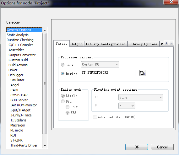
Use IAR to open the APP project and change the device to STM32F070:
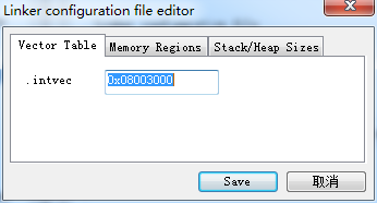
Link configuration:
Interrupt vector table:
Memory Map:
As above, the APP is stored in the FLASH location 0x8003000, and the memory is still set to: 0x20000000.
After compilation, open the corresponding map file as shown below:
Entry Address Size Type Object
----- ------- ---- ---- ------
.iar.init_table$$Base 0x080034fc -- Gb - Linker created -
.iar.init_table$$Limit 0x08003510 -- Gb - Linker created -
?main 0x08003511 Code Gb cmain.o [4]
CSTACK$$Base 0x200000d8 -- Gb - Linker created -
CSTACK$$Limit 0x200010d8 -- Gb - Linker created -
Delay 0x080031e3 0x10 Code Gb main.o [1]
GPIO_PIN 0x080035a0 0x8 Data Gb stm320518_eval.o [1]
GPIO_PORT 0x200000c0 0x10 Data Gb stm320518_eval.o [1] //The global variable GPIO_PORT array in the stm320518_eval.c file is stored at 0x200000c0
HardFault_Handler 0x08003573 0x4 Code Gb stm32f0xx_it.o [1]
NMI_Handler 0x08003571 0x2 Code Gb stm32f0xx_it.o [1]
NVIC_SetPriority 0x080030c1 0x84 Code Lc main.o [1]
PendSV_Handler 0x08003579 0x2 Code Gb stm32f0xx_it.o [1]
RCC_APB2PeriphClockCmd 0x08003229 0x20 Code Gb stm32f0xx_rcc.o [1]
RegionBase 0x080034fc -- Gb - Linker created -
RegionLimit 0x08003510 -- Gb - Linker created -
STM_EVAL_LEDToggle 0x08003315 0x26 Code Gb stm320518_eval.o [1]
SVC_Handler 0x08003577 0x2 Code Gb stm32f0xx_it.o [1]
SYSCFG_MemoryRemapConfig
0x0800324d 0x14 Code Gb stm32f0xx_syscfg.o [1]
SetSysClock 0x080033b7 0xbe Code Lc system_stm32f0xx.o [1]
SysTick_Config 0x08003145 0x32 Code Lc main.o [1]
SysTick_Handler 0x0800357b 0x8 Code Gb stm32f0xx_it.o [1]
SystemCoreClock 0x200000d0 0x4 Data Gb system_stm32f0xx.o [1]
SystemInit 0x08003349 0x6e Code Gb system_stm32f0xx.o [1]
TimingDelay 0x200000d4 0x4 Data Lc main.o [1]
TimingDelay_Decrement 0x080031f3 0x16 Code Gb main.o [1]
VectorTable 0x20000000 0xc0 Data Gb main.o [1] //The vector table is compiled at 0x20000000
__aeabi_idiv0 0x08003345 Code Gb IntDivZer.o [4]
__aeabi_uidiv 0x08003265 Code Gb I32DivModFast.o [4]
__aeabi_uidivmod 0x08003265 Code Gb I32DivModFast.o [4]
__cmain 0x08003511 Code Gb cmain.o [4]
__exit 0x08003545 0x14 Code Gb exit.o [5]
__iar_copy_init3 0x080034a5 0x30 Code Gb copy_init3.o [4]
__iar_data_init3 0x080034d5 0x28 Code Gb data_init.o [4]
__iar_program_start 0x08003595 Code Gb cstartup_M.o [4]
__low_level_init 0x0800352b 0x4 Code Gb low_level_init.o [3]
__vector_table 0x08003000 Data Gb startup_stm32f0xx.o [1]
_call_main 0x0800351d Code Gb cmain.o [4]
_exit 0x08003539 Code Gb cexit.o [4]
_main 0x08003527 Code Gb cmain.o [4]
exit 0x0800352f 0x8 Code Gb exit.o [3]
main 0x08003177 0x6c Code Gb main.o [1]
As shown above, under IAR compilation, the interrupt vector table is compiled at 0x20000000, the starting position of the memory, and the global variable GPIO_PORT under stm320518_eval.c is compiled by IAR to be placed at the next position 0x200000C0. Burn IAP and APP into FLASH respectively, and the test can run normally.
Note: From the link configuration of the IAR project, the RAM location is not configured as 0x2000000 like KEIL, and the resulting vector table after compilation will not conflict with other global variables. It can be seen that the IAR compiler has automatically calculated and avoided this conflict, unlike KEIL, which will not cause a link error to prompt the user.
In addition: Under IAR, you can debug the APP even if there is no IAP. This is a feature that KEIL does not have. It seems that IAR is better than KEIL in handling details.
Previous article:Detailed explanation of hex file stm32
Next article:STM32F030 ADC1 DMA sampling problem
Recommended ReadingLatest update time:2024-11-16 19:31

 Professor at Beihang University, dedicated to promoting microcontrollers and embedded systems for over 20 years.
- Innolux's intelligent steer-by-wire solution makes cars smarter and safer
- 8051 MCU - Parity Check
- How to efficiently balance the sensitivity of tactile sensing interfaces
- What should I do if the servo motor shakes? What causes the servo motor to shake quickly?
- 【Brushless Motor】Analysis of three-phase BLDC motor and sharing of two popular development boards
- Midea Industrial Technology's subsidiaries Clou Electronics and Hekang New Energy jointly appeared at the Munich Battery Energy Storage Exhibition and Solar Energy Exhibition
- Guoxin Sichen | Application of ferroelectric memory PB85RS2MC in power battery management, with a capacity of 2M
- Analysis of common faults of frequency converter
- In a head-on competition with Qualcomm, what kind of cockpit products has Intel come up with?
- Dalian Rongke's all-vanadium liquid flow battery energy storage equipment industrialization project has entered the sprint stage before production
- Allegro MicroSystems Introduces Advanced Magnetic and Inductive Position Sensing Solutions at Electronica 2024
- Car key in the left hand, liveness detection radar in the right hand, UWB is imperative for cars!
- After a decade of rapid development, domestic CIS has entered the market
- Aegis Dagger Battery + Thor EM-i Super Hybrid, Geely New Energy has thrown out two "king bombs"
- A brief discussion on functional safety - fault, error, and failure
- In the smart car 2.0 cycle, these core industry chains are facing major opportunities!
- The United States and Japan are developing new batteries. CATL faces challenges? How should China's new energy battery industry respond?
- Murata launches high-precision 6-axis inertial sensor for automobiles
- Ford patents pre-charge alarm to help save costs and respond to emergencies
- New real-time microcontroller system from Texas Instruments enables smarter processing in automotive and industrial applications
- [RISC-V MCU CH32V103 Evaluation] W25Q16 Reading, Writing and Application
- 【GD32E231 DIY Contest】1. USART0
- When a plane crashes, is there any technology that can completely guarantee the safety of passengers?
- STMicroelectronics launches the second generation multi-zone time-of-flight sensor VL53L8
- EEWORLD University - Wildfire FreeRTOS Kernel Implementation and Application Development Practical Guide
- Teach you how to make a lithium battery fast charging charger
- Solution to the problem of not being able to generate electrical connection network using Harness in Altium Designer
- 【ufun learning】02 Concept and preliminary circuit design 1
- 【RT-Thread Reading Notes】Reflections on RT-Thread Chapters 7-8
- DC-DC chip LM2596SX-5.0/NOPB

 FreeRTOS kernel implementation and application development practical guide: based on STM32
 Arduino Development Guide: STM32


 京公网安备 11010802033920号