Purpose:
Print the time the key is pressed on the serial debugging assistant
Experimental steps:
Experimental Procedure:
/*******************************timer.c********************************/
#include "sys.h"
#include "stm32f4xx.h"
extern u8 TIM5CHA1_CAPTURE_STA;
extern u16 TIM5CHA1_CAPTURE_VAL;
/*
The purpose of this example is to
When a key is pressed, the time difference between each input capture,
Then print out the time difference from the serial port debugging assistant;
*/
/*
For input capture operations, please refer to the steps in the register version.
*/
/*
Initialization function of timer input capture:
Mainly about the configuration of registers
*/
/*Initialize timer 5 as input capture*/
void TIM5_Init(void){
/*************************
Timer input capture settings:
*************************/
/*Reuse the KEY_UP button*/
/*1. Enable GPIO port clock*/
RCC->AHB1ENR |= 1;
/*Here you also need to configure it to pull down,
Because in input capture, it will be triggered by the rising edge;
*/
GPIOA->PUPDR |= 0X2;
/*2. Enable multiplexing peripheral clock*/
RCC->APB1ENR |= 1<<3;
/*3.Port mode is configured as multiplexing function*/
GPIOA->MODER |= 0X2;
/*4. Configure GPIOx_AFRL or GPIOx_AFRH register,
Connect the IO to the desired multiplexed peripheral */
GPIOA->AFR[0] |= 0X2;
/*Set up input capture of timer 5*/
//Set the frequency division and automatic reload of TIM5
TIM5->PSC = 84-1;
TIM5->ARR = 0XFFFF-1; //The chip manual says it is 16 bits.
//Set filtering/mapping/frequency division
TIM5->CCMR1 |= 0X1;
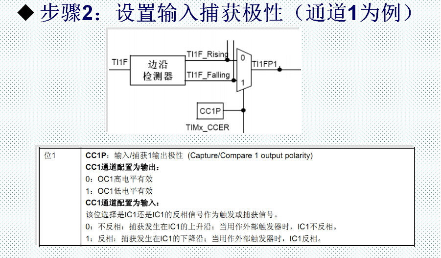
//Set the rising edge trigger and enable capture
TIM5->CCER |= 0X1;
// Enable update interrupt and capture interrupt
TIM5->DIER |= 0X3;
// Enable the counter
TIM5->CR1 |= 1;
//Set interrupt priority
SCB->AIRCR |= 0x5 << 8; //Set group
NVIC->IP[50] |= 0; //Set the priority, for details, please analyze the MY_NVIC_Init() function;
//As long as interrupts are involved, remember to enable interrupts at the end;
//If not enabled, the interrupt will not occur
NVIC->ISER[1] |= 1<<18; //Enable interrupt;
}
/*Each time a key is pressed, input captures the key.
Then every time an interrupt occurs twice,
Calculate the time difference between the two captures;
*/
void TIM5_IRQHandler(void){
/*
Interrupt handling function:
*/
if((TIM5CHA1_CAPTURE_STA & 0x80) != 0x80){ //Indicates that a complete input capture has not yet ended;
if((TIM5->SR & 0X1) == 0X1){ //Indicates that an overflow flag has occurred
if((TIM5CHA1_CAPTURE_STA & 0x40) == 0x40){ //Only after capturing a high level,
//We accumulate the value of the counter
if((TIM5CHA1_CAPTURE_STA & 0x3f)==0x3f){ //Indicates that the cumulative counter is full;
//Here, the high level lasts for a maximum of 4 seconds
TIM5CHA1_CAPTURE_STA |= 0x80;
TIM5CHA1_CAPTURE_VAL = 0xffff;
}else{
TIM5CHA1_CAPTURE_STA++;
}
}
}
if((TIM5->SR & 0X2) == 0X2){ //Indicates that the rising edge or falling edge has been captured
if((TIM5CHA1_CAPTURE_STA & 0x40) == 0x40){ //Indicates that the falling edge has been triggered
TIM5CHA1_CAPTURE_STA |= 0x80 ; //Indicates that the capture of one cycle of rising and falling edges has been completed;
TIM5CHA1_CAPTURE_VAL = TIM5->CCR1; //Save the value of the counter when the falling edge trigger occurs;
//Set the rising edge trigger and enable capture
TIM5->CCER &= ~(1<<1);
}else{ //Indicates that the rising edge has been captured
//Disable the counter of timer 5
TIM5->CR1 &= ~(1);
//Let the counter value be 0 so as to calculate the value from 0 to the value captured by the next falling edge;
TIM5->CNT = 0;
//Set input capture to falling edge trigger
TIM5->CCER &= ~(0XF);
TIM5->CCER |= 0X3;
//Initialize the value to be counted;
TIM5CHA1_CAPTURE_STA = 0;
TIM5CHA1_CAPTURE_STA |= 0X40;
TIM5CHA1_CAPTURE_VAL = 0;
// Enable the counter
TIM5->CR1 |= 1;
}
}
}
/*
Finally, remember to clear the interrupt flag in the interrupt:
*/
TIM5->SR &= ~(0x3);
}
/*******************************timer.h*********************************/
#ifndef _EXIT_H
#define _EXTI_H
void TIM5_Init(void);
#endif
/*******************************test.c***********************************/
#include "sys.h"
#include "delay.h"
#include "beep.h"
#include "exti.h"
#include "led.h"
#include "uart.h"
#include "usart.h"
u8 TIM5CHA1_CAPTURE_STA;
u32 TIM5CHA1_CAPTURE_VAL;
int main(void){
u8 i = 0;
long long temp = 0; //The value here is relatively large, so choose long long
Stm32_Clock_Init(336,8,2,7); //Set the clock, 168Mhz
delay_init(168); //Initialize delay function
LED_Heat();
Beep_Init();
TIM5_Init();
UART_Init();
while(1){
PFout(9) = 0;
delay_ms(500);
PFout(9) = 1;
delay_ms(500);
if((TIM5CHA1_CAPTURE_STA & 0x80) == 0x80){ //If a complete capture cycle (rising edge and falling edge)
i = TIM5CHA1_CAPTURE_STA & 0x3f;
printf("TIM5:%d\r\n",i);
//Calculate the accumulated time (the time difference between high level and low level)
temp = (TIM5CHA1_CAPTURE_STA & 0x3f)*0xffff;
temp += TIM5CHA1_CAPTURE_VAL;
printf("temp:%lld us\r\n",temp); //Think about how the printf() function works;
//Reinitialize
TIM5CHA1_CAPTURE_STA = 0;
TIM5CHA1_CAPTURE_VAL = 0;
}
}
}
experiment analysis:
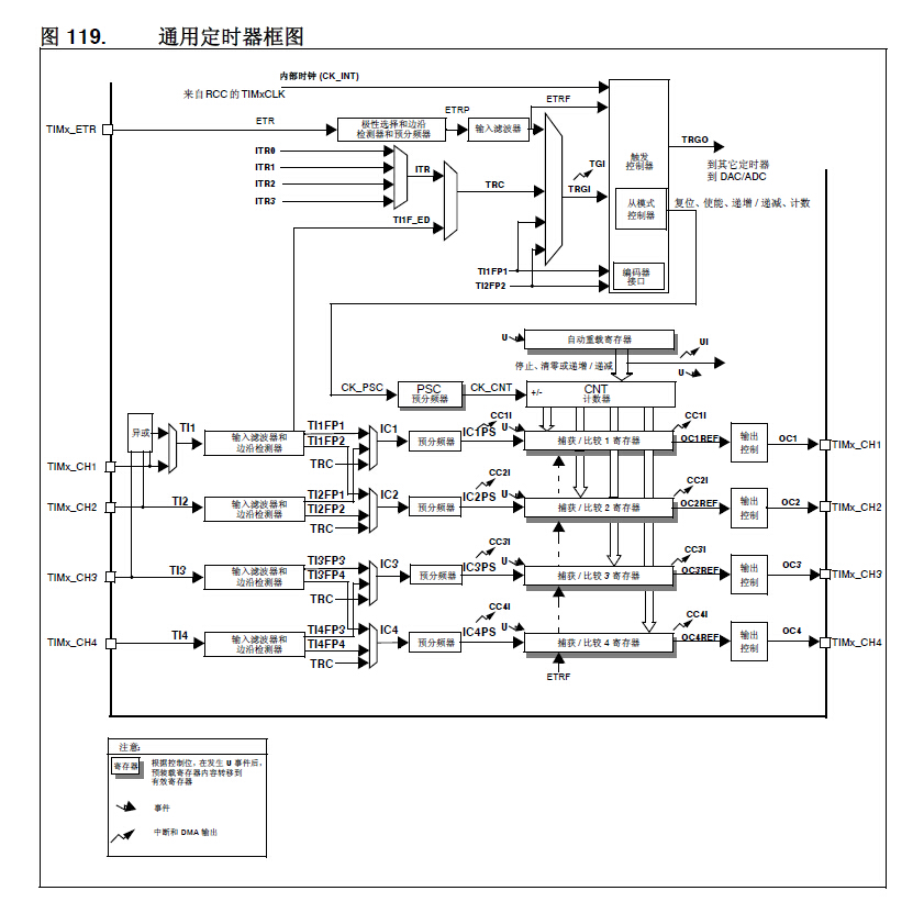
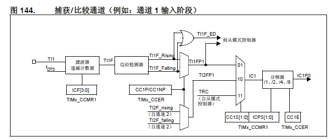
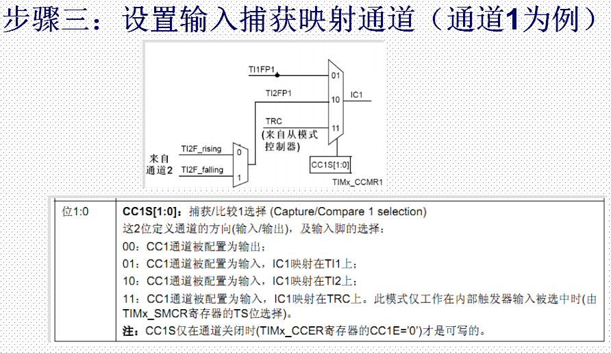
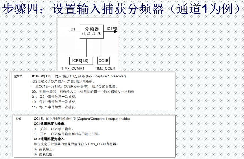
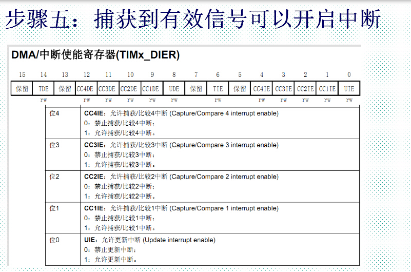
1. Block diagram of the timer and enlarged version of the input capture block diagram
Note: By detecting the edge signal on TIMx_CHx, when the edge signal changes (such as rising edge/falling edge),
Store the current timer value (TIMx_CNT) into the corresponding capture/compare register (TIMx_CCRx) to complete a capture.
2. Input capture workflow analysis:
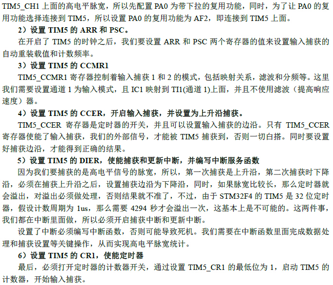
<1>
<2>
<3>
<4>
<5>
3. Tips for interrupt handling functions
Precautions:
1. As long as interrupts are involved, you must remember to enable interrupts at the end
2. The key processing is not very good, sometimes it will type several strings of numbers in a row;
To be more precise, the key sometimes jitters a bit, which is equivalent to pressing it several times, but not filtering out the smaller part of the band;
Previous article:STM32 learning notes timer input capture experiment
Next article:STM32 timer interrupt
Recommended ReadingLatest update time:2024-11-16 11:49


- Popular Resources
- Popular amplifiers
 Professor at Beihang University, dedicated to promoting microcontrollers and embedded systems for over 20 years.
- Innolux's intelligent steer-by-wire solution makes cars smarter and safer
- 8051 MCU - Parity Check
- How to efficiently balance the sensitivity of tactile sensing interfaces
- What should I do if the servo motor shakes? What causes the servo motor to shake quickly?
- 【Brushless Motor】Analysis of three-phase BLDC motor and sharing of two popular development boards
- Midea Industrial Technology's subsidiaries Clou Electronics and Hekang New Energy jointly appeared at the Munich Battery Energy Storage Exhibition and Solar Energy Exhibition
- Guoxin Sichen | Application of ferroelectric memory PB85RS2MC in power battery management, with a capacity of 2M
- Analysis of common faults of frequency converter
- In a head-on competition with Qualcomm, what kind of cockpit products has Intel come up with?
- Dalian Rongke's all-vanadium liquid flow battery energy storage equipment industrialization project has entered the sprint stage before production
- Allegro MicroSystems Introduces Advanced Magnetic and Inductive Position Sensing Solutions at Electronica 2024
- Car key in the left hand, liveness detection radar in the right hand, UWB is imperative for cars!
- After a decade of rapid development, domestic CIS has entered the market
- Aegis Dagger Battery + Thor EM-i Super Hybrid, Geely New Energy has thrown out two "king bombs"
- A brief discussion on functional safety - fault, error, and failure
- In the smart car 2.0 cycle, these core industry chains are facing major opportunities!
- The United States and Japan are developing new batteries. CATL faces challenges? How should China's new energy battery industry respond?
- Murata launches high-precision 6-axis inertial sensor for automobiles
- Ford patents pre-charge alarm to help save costs and respond to emergencies
- New real-time microcontroller system from Texas Instruments enables smarter processing in automotive and industrial applications
- Domestic FPGA Sipeed Tang Nano 4K camera HDMI display routine is also running
- Shanghai Pudong + Suzhou-Recruiting RF IC engineers and analog IC layout engineers
- How to solve the problem that the ADC reading of MSP432 is affected by external electrical appliances?
- Last 3 days, come if you are brave | Infineon IGBT7 escape room, you are invited to play!
- Play with Beidou short messages and Beidou positioning with pictures and texts
- ADC and DAC Special Study.pdf
- Taking the BOOST circuit as an example, there are two algorithms to calculate the maximum average input current, that is, the inductor current.
- Looking for a current/voltage limiting IC
- [AutoChips AC7801x motor demo board review] + Write Hall sensor BLDC square wave control from scratch
- Signal correlation operations and algorithm analysis in single chip microcomputer program application (Part 2)




 usb_host_device_code
 Transplantation of real-time operating system RT-ThreadSmart on STM32MP1


 京公网安备 11010802033920号