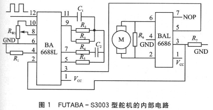
The servo is a position servo driver. It receives a certain control signal and outputs a certain angle. It is suitable for control systems that require the angle to change continuously and be maintained. In micro-electromechanical systems and aircraft models, it is a basic output actuator. Taking the FUTABA-S3003 servo as an example, Figure 1 is the internal circuit of the FUFABA-S3003 servo .
The working principle of the servo is: The PWM signal enters the signal demodulation circuit BA66881 from the receiving channel. It is demodulated at the 12th foot to obtain a DC bias voltage . The DC bias voltage is compared with the voltage of the potentiometer, and the voltage difference is output by the 3rd foot of BA6688. The output is sent to the motor driver integrated circuit BA6686 to drive the motor forward and reverse. When the motor speed is constant, the potentiometer R is driven by the cascade reduction gear. Rotate until the voltage difference is 0 and the motor stops. The control signal of the servo is a PWM signal, which changes the position of the servo by changing the duty cycle.

Control method of servo
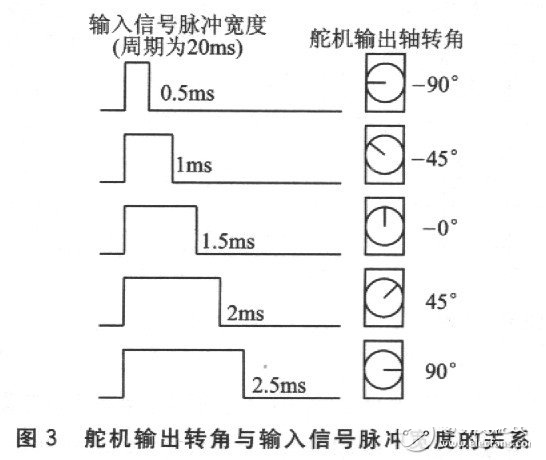
The power line and ground line are used to provide energy for the DC motor and control circuit inside the servo. The voltage is usually between 4 and 6V, and 5V is generally used. Note that the power supply to the servo should be able to provide sufficient power. The input of the control line is a periodic square wave pulse signal with adjustable width. The period of the square wave pulse signal is 20 ms (that is, the frequency is 50 Hz). When the pulse width of the square wave changes, the angle of the servo shaft changes, and the angle change is proportional to the change in pulse width. The relationship between the output shaft angle of a certain type of servo and the pulse width of the input signal can be expressed by 3.

Hardware circuit design of servo controller
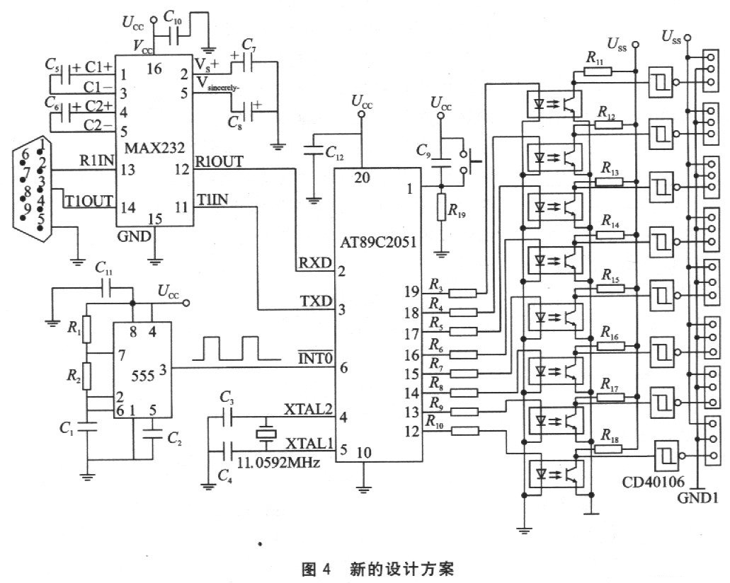
From the above control method of servo angle, it can be seen that the control signal of the servo is actually a square wave signal (PWM) with adjustable width. The square wave signal can be generated by FPGA , analog circuit or single-chip microcomputer . The cost of using FPGA is high, and the circuit is more complicated when implemented by analog circuit, which is not suitable for multi-channel output. Single-chip microcomputer is generally used as the controller of the servo. At present, there are many schemes using single-chip microcomputers as servo controllers. PWM can be realized by using the timer interrupt of the single-chip microcomputer. This scheme divides the 20ms periodic signal into two timing interrupts: one timing to realize high-level timing Th; one timing to realize low-level timing T1. The time values of Th and T1 change with the change of pulse width, but Th+T1=20ms. The advantage of this method is that the PWM signal is completely realized by the interrupt of the internal timer of the single-chip microcomputer, and no peripheral hardware needs to be added. The disadvantage is that the PWM signal in one cycle must be completed by two interrupts, and the calculation of the timing values of the two interrupts is more troublesome; in order to meet the 20ms cycle, the frequency of the single-chip microcomputer crystal oscillator must be reduced; multiple outputs cannot be realized. The implementation scheme of single-chip microcomputer + 8253 counter can also be used. This scheme generates counting pulses from the single-chip microcomputer (or the external circuit generates counting pulses) and provides them to 8253 for counting, and the single-chip microcomputer gives the counting comparison value of 8253 to change the output pulse width. The advantage of this scheme is that multiple outputs can be realized and the software design is relatively simple; the disadvantage is that an 8253 counter needs to be added, which increases the hardware cost. Based on the above two MCU servo control schemes, this paper proposes a new design scheme, as shown in Figure 4.

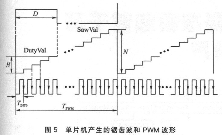
The servo controller of this scheme is based on the AT89C2051 ($0.5940) MCU as the core, and the oscillator composed of 555 is used as the timing reference. The MCU generates PWM signals by counting the pulse signals generated by the 555 oscillator. The MCU in this controller can generate 8 channels of PWM signals, which are output by the P1.0~Pl.7 (12~19 pins) ports of AT89C2051. The output 8-channel PWM signals are transmitted to the next level circuit through optocoupler isolation. Because the signal is inverted during the transmission process through the optocoupler, the signal from the optocoupler must be inverted again through the inverter. After the square wave signal is transmitted through the optocoupler, the leading and trailing edges will be distorted, so the inverter uses the CD40106 ($0.1125) Schmidt inverter to shape the signal transmitted by the optocoupler to generate a standard PWM square wave signal. During the experiment, the author found that the servo absorbs a large current from the power supply during operation . If the servo and the single-chip controller share a power supply, the servo will cause greater interference to the single-chip. Therefore, the servo and the single-chip controller are powered by two power supplies, which are not grounded and isolated by optocouplers. In addition, the power supply for the servo is preferably a switching power supply with a large output power . The servo controller occupies an SCI serial port of the single-chip microcomputer. The serial port is used to receive control commands sent by the host computer to adjust the pulse width of the output signal of each channel. MAX232 ($2.0686) is a level converter that converts the RS232 ($780.5000) level of the host computer into a TTL level. Principle of realizing multi-channel PWM signals In analog circuits, PWM pulse signals can be obtained by comparing the DC level with the sawtooth wave signal. In the single-chip microcomputer, the sawtooth wave can be realized by adding 1 to the integer variable, as shown in Figure 5. Assume that an integer variable SawVal is set in the single-chip microcomputer program, and its value range is O~N. The external counting clock signal generated by the 555 oscillation circuit is input to the INTO pin of AT89C2051. Whenever the external counting clock pulse falls, the microcontroller generates an external interrupt and executes the interrupt service program of the external interrupt INT0. Every time an external interrupt is generated, an addition operation is performed on SawVal. If SawVal has reached the maximum value N, SawVal is cleared to 0. The change pattern of the SawVal value is equivalent to a sawtooth wave, as shown in Figure 5. If another integer variable DutyVal is set in the microcontroller program, its value range is O~N. Whenever SawVal is cleared to 0, DulyVal reads the pulse width coefficient value from the control command sent by the host computer, for example, H (0≤H≤N). If DutyVal≥SawVal, the corresponding port outputs a high level; if DutyVal

Keywords:AT89C2051
Reference address:Detailed explanation of AT89C2051 multi-channel servo control circuit
The working principle of the servo is: The PWM signal enters the signal demodulation circuit BA66881 from the receiving channel. It is demodulated at the 12th foot to obtain a DC bias voltage . The DC bias voltage is compared with the voltage of the potentiometer, and the voltage difference is output by the 3rd foot of BA6688. The output is sent to the motor driver integrated circuit BA6686 to drive the motor forward and reverse. When the motor speed is constant, the potentiometer R is driven by the cascade reduction gear. Rotate until the voltage difference is 0 and the motor stops. The control signal of the servo is a PWM signal, which changes the position of the servo by changing the duty cycle.

Control method of servo
The power line and ground line are used to provide energy for the DC motor and control circuit inside the servo. The voltage is usually between 4 and 6V, and 5V is generally used. Note that the power supply to the servo should be able to provide sufficient power. The input of the control line is a periodic square wave pulse signal with adjustable width. The period of the square wave pulse signal is 20 ms (that is, the frequency is 50 Hz). When the pulse width of the square wave changes, the angle of the servo shaft changes, and the angle change is proportional to the change in pulse width. The relationship between the output shaft angle of a certain type of servo and the pulse width of the input signal can be expressed by 3.

Hardware circuit design of servo controller
From the above control method of servo angle, it can be seen that the control signal of the servo is actually a square wave signal (PWM) with adjustable width. The square wave signal can be generated by FPGA , analog circuit or single-chip microcomputer . The cost of using FPGA is high, and the circuit is more complicated when implemented by analog circuit, which is not suitable for multi-channel output. Single-chip microcomputer is generally used as the controller of the servo. At present, there are many schemes using single-chip microcomputers as servo controllers. PWM can be realized by using the timer interrupt of the single-chip microcomputer. This scheme divides the 20ms periodic signal into two timing interrupts: one timing to realize high-level timing Th; one timing to realize low-level timing T1. The time values of Th and T1 change with the change of pulse width, but Th+T1=20ms. The advantage of this method is that the PWM signal is completely realized by the interrupt of the internal timer of the single-chip microcomputer, and no peripheral hardware needs to be added. The disadvantage is that the PWM signal in one cycle must be completed by two interrupts, and the calculation of the timing values of the two interrupts is more troublesome; in order to meet the 20ms cycle, the frequency of the single-chip microcomputer crystal oscillator must be reduced; multiple outputs cannot be realized. The implementation scheme of single-chip microcomputer + 8253 counter can also be used. This scheme generates counting pulses from the single-chip microcomputer (or the external circuit generates counting pulses) and provides them to 8253 for counting, and the single-chip microcomputer gives the counting comparison value of 8253 to change the output pulse width. The advantage of this scheme is that multiple outputs can be realized and the software design is relatively simple; the disadvantage is that an 8253 counter needs to be added, which increases the hardware cost. Based on the above two MCU servo control schemes, this paper proposes a new design scheme, as shown in Figure 4.

The servo controller of this scheme is based on the AT89C2051 ($0.5940) MCU as the core, and the oscillator composed of 555 is used as the timing reference. The MCU generates PWM signals by counting the pulse signals generated by the 555 oscillator. The MCU in this controller can generate 8 channels of PWM signals, which are output by the P1.0~Pl.7 (12~19 pins) ports of AT89C2051. The output 8-channel PWM signals are transmitted to the next level circuit through optocoupler isolation. Because the signal is inverted during the transmission process through the optocoupler, the signal from the optocoupler must be inverted again through the inverter. After the square wave signal is transmitted through the optocoupler, the leading and trailing edges will be distorted, so the inverter uses the CD40106 ($0.1125) Schmidt inverter to shape the signal transmitted by the optocoupler to generate a standard PWM square wave signal. During the experiment, the author found that the servo absorbs a large current from the power supply during operation . If the servo and the single-chip controller share a power supply, the servo will cause greater interference to the single-chip. Therefore, the servo and the single-chip controller are powered by two power supplies, which are not grounded and isolated by optocouplers. In addition, the power supply for the servo is preferably a switching power supply with a large output power . The servo controller occupies an SCI serial port of the single-chip microcomputer. The serial port is used to receive control commands sent by the host computer to adjust the pulse width of the output signal of each channel. MAX232 ($2.0686) is a level converter that converts the RS232 ($780.5000) level of the host computer into a TTL level. Principle of realizing multi-channel PWM signals In analog circuits, PWM pulse signals can be obtained by comparing the DC level with the sawtooth wave signal. In the single-chip microcomputer, the sawtooth wave can be realized by adding 1 to the integer variable, as shown in Figure 5. Assume that an integer variable SawVal is set in the single-chip microcomputer program, and its value range is O~N. The external counting clock signal generated by the 555 oscillation circuit is input to the INTO pin of AT89C2051. Whenever the external counting clock pulse falls, the microcontroller generates an external interrupt and executes the interrupt service program of the external interrupt INT0. Every time an external interrupt is generated, an addition operation is performed on SawVal. If SawVal has reached the maximum value N, SawVal is cleared to 0. The change pattern of the SawVal value is equivalent to a sawtooth wave, as shown in Figure 5. If another integer variable DutyVal is set in the microcontroller program, its value range is O~N. Whenever SawVal is cleared to 0, DulyVal reads the pulse width coefficient value from the control command sent by the host computer, for example, H (0≤H≤N). If DutyVal≥SawVal, the corresponding port outputs a high level; if DutyVal

Previous article:Design of high-gain data acquisition system based on USB interface
Next article:Design of a Home Security System Based on AT89S52 and CAN Bus
- Popular Resources
- Popular amplifiers
Recommended Content
Latest Microcontroller Articles
He Limin Column
Microcontroller and Embedded Systems Bible
 Professor at Beihang University, dedicated to promoting microcontrollers and embedded systems for over 20 years.
MoreSelected Circuit Diagrams
MorePopular Articles
- LED chemical incompatibility test to see which chemicals LEDs can be used with
- Application of ARM9 hardware coprocessor on WinCE embedded motherboard
- What are the key points for selecting rotor flowmeter?
- LM317 high power charger circuit
- A brief analysis of Embest's application and development of embedded medical devices
- Single-phase RC protection circuit
- stm32 PVD programmable voltage monitor
- Introduction and measurement of edge trigger and level trigger of 51 single chip microcomputer
- Improved design of Linux system software shell protection technology
- What to do if the ABB robot protection device stops
MoreDaily News
- Download from the Internet--ARM Getting Started Notes
- Learn ARM development(22)
- Learn ARM development(21)
- Learn ARM development(20)
- Learn ARM development(19)
- Learn ARM development(14)
- Learn ARM development(15)
- Analysis of the application of several common contact parts in high-voltage connectors of new energy vehicles
- Wiring harness durability test and contact voltage drop test method
- From probes to power supplies, Tektronix is leading the way in comprehensive innovation in power electronics testing
Guess you like
- Will SiC replace IGBT? Let's discuss it together.
- Arduino is about to release the Portenta H7 development board
- [Zero-knowledge ESP8266 tutorial] Advanced 1 WIFI MESH networking example
- [Industrial Equipment Edge Intelligence Solution] Part 2: Low-power 3-axis accelerometer + 3-axis gyroscope + Bluetooth debugging
- Does ON Semiconductor's device have no AD library?
- Highlight Review丨What hard-core technologies did ADI demonstrate at IMS 2019?
- DMA and interrupt implementation of PCI data acquisition card.pdf
- Negative power supply design
- [Smart Elderly Assisted Seat] Material Unboxing—stm32f7508-DK and stm32f767
- Wenqiao

 OPA37EZ-BI


 京公网安备 11010802033920号