1 Introduction
With the accelerated development of China's transportation infrastructure construction, the traffic volume is growing rapidly, and with it comes road congestion, air pollution, and the harm caused by traffic accidents. In order to alleviate road congestion, improve travel conditions, and improve road safety, the intelligent traffic control system, as a non-site law enforcement means, can quickly monitor, capture, and remotely transmit various illegal phenomena such as running red lights, speeding, driving in the wrong direction, changing lanes illegally, and crossing yellow lines. In order to quickly obtain evidence of violations and deal with traffic violations in a timely manner, it provides an effective monitoring method and plays a positive role in reducing and avoiding traffic accidents. Therefore, the vehicle detector developed in the article is to provide sufficient information for the intelligent traffic control system for optimal control. From the application form of the intelligent traffic control system, it can be seen that the intelligent vehicle detector is an important part of traffic information collection.
2 Vehicle detector
The vehicle detector is an indispensable part of the highway and urban traffic road monitoring system. It mainly provides various traffic parameters to the information processing and information release units in the monitoring system through data collection and equipment monitoring. It serves as the main basis for the monitoring center to analyze, judge, issue information, and propose control plans. Therefore, the level of vehicle detectors and their detection technology directly affects the overall operation and management level of the highway traffic monitoring system. The
toroidal coil vehicle detector we currently use on site is a vehicle detector based on the principle of electromagnetic induction. Its sensor is a toroidal coil (generally 2 meters x 1 meter) buried under the road surface and passed with a certain operating current . When a vehicle passes through the toroidal buried coil or stops on the toroidal buried coil, the vehicle's own iron cuts the magnetic flux line, causing the change of the inductance wall of the line. The detector can detect the presence of the vehicle by detecting the change in inductance. There are generally two ways to detect this inductance change: one is to use a phase latch and a phase comparator to detect the change in phase. The other way is to use a coupling circuit composed of a loop of toroidal buried coils to detect its oscillation frequency. We use the latter detection method here. Under normal circumstances, when the motor vehicle is not at the location of the toroidal buried coil, the oscillation frequency of the coupling circuit remains constant. The number of pulses measured in a unit time period remains basically unchanged. When the motor vehicle passes the location of the toroidal buried coil, due to the increase in the oscillation frequency of the coupling circuit, the toroidal buried coil is detected. The number of pulses measured by the microcontroller in a unit time period also increases accordingly. When there is no motor vehicle at the location of the buried coil, the number of pulses measured by the microcontroller in a unit time period is PN. When a motor vehicle passes the location of the buried coil, the number of pulses measured by the microcontroller in a unit time period is PM. The pulse increment △E is the difference between PM and PN, that is, △E=PM-PN. The empirical threshold △T of the pulse increment is pre-set in the EEPROM. When △E≥△T, it is considered that there is a car. When △E<△T, it is considered that there is no car, thereby judging whether there is a vehicle passing through the current lane.
3 Vehicle detector hardware design
The vehicle detector is an application system based on the C8051F121 chip as shown in Figure 1. Each channel is enabled to generate an oscillation signal after being selected by the 74HC18 three-wire decoding chip. The oscillation signal generated by the circuit shown in Figure 2 is then shaped by the integrated operation LM293 shaping circuit (Figure 3) to form a pulse signal and sent to the ECI pin of the C8051F121 chip. The programmable counter and capture module function are used to start the timer T0 to count the pulse signal and determine whether there is a vehicle passing through the current lane. When a vehicle passes by, the vehicle status is displayed on the panel of the vehicle detector and converted into a standard RS232 signal through the UART0 interface of the C8051Fl21 chip via the MAX202 serial port chip (Figure 4). The vehicle status data is sent to the host computer and processed by the background software to realize the function of capturing illegal vehicles. In the application, the RS422 signal sent from the red light signal board is sent to the UARTI interface of the C8051F121 chip after being converted by the MAX488 chip. The received data is then sent to the host computer through the UART0 interface.
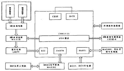
Figure 1 Schematic diagram of vehicle detector
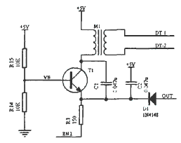
Figure 2 Oscillator circuit
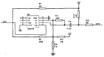
Figure 3 Pulse shaping circuit
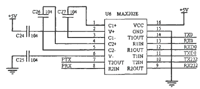
Figure 4 RS232 level conversion circuit
Working mode of vehicle detector: Programmable counter array (PCAO) can provide enhanced timer function. It requires less CPU intervention. PCAO contains a dedicated 16-bit counter, timer and 6 16-bit capture/compare modules (CEXn) and each capture/compare module has its own I/O line. This device uses CEX0 module, which is programmed as an independent working mode of 8-bit pulse modulation ( PWM ) output. When the low byte (PCAOL) of PCAO counter/timer is equal to the value in PCAOCPL0, the output of CEXO is high. When the count value in PCAOL overflows, the output of CEXO is set to low. When the low byte PCAOL of counter/timer overflows from 0xFF to 0x00, the value stored in the high byte (PCAOCPLHO) of counter/timer is automatically loaded into PCAOCPLO without software intervention. The pulse signal (EC1) of the external channel oscillator output signal shaped by the pulse shaping circuit is selected as the time base of programmable counting PCA.
4 Vehicle detector software design
In the process of Figure 5, it can be seen that the output frequency of the oscillating circuit using the ground sensor coil as the vehicle sampling is shaped by LM393 as the input pulse of ECl0, and the negative jump of ECI is effective. When the output of CEX0 is 1 (i.e. /INTO=1) and TR0=1, the timer counting function is started. The pulses input to ECl0 are counted in the corresponding time period. As the current vehicle sampling value, it is compared with the initialization value (when there is no vehicle) and the experience value when the system is running. It is thus determined whether there is a vehicle passing through the ground sensor coil in the current lane. When a vehicle passes and is detected, the vehicle status data is updated in time. At the same time, it is displayed on the panel of the vehicle detector and sent to COM1 of the embedded computer system through the RS232 port (COM1 port of the board). The background software receives the vehicle status signal and determines that it is in the red light signal time period. The digital camera is started according to the set violation phenomenon, and the capture command is sent through the USB data cable. Thus, three consecutive pictures of the illegal vehicle are obtained.
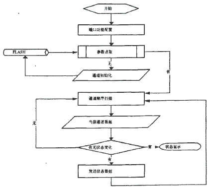
Figure 5 Basic flow chart
5 Conclusion
The toroidal coil vehicle detector is the most widely used vehicle detector in the world. It has become the most popular vehicle detector with its mature technology, easy to master, and accurate counting. This article is based on the hardware platform of the CIP-51TM microcontroller core system on chip (SOC) C8051F121 chip of Silicon Lab, USA. The hardware circuit design, interface circuit design and software design of the device are comprehensively discussed and studied in this article. The experimental results show that the device has the characteristics of low power consumption, low cost and powerful functions. It makes full use of the resources provided by the chip and meets the needs of intelligent vehicle detectors.
Keywords:C8051F121
Reference address:Design and application of intelligent vehicle detector based on C8051F121
With the accelerated development of China's transportation infrastructure construction, the traffic volume is growing rapidly, and with it comes road congestion, air pollution, and the harm caused by traffic accidents. In order to alleviate road congestion, improve travel conditions, and improve road safety, the intelligent traffic control system, as a non-site law enforcement means, can quickly monitor, capture, and remotely transmit various illegal phenomena such as running red lights, speeding, driving in the wrong direction, changing lanes illegally, and crossing yellow lines. In order to quickly obtain evidence of violations and deal with traffic violations in a timely manner, it provides an effective monitoring method and plays a positive role in reducing and avoiding traffic accidents. Therefore, the vehicle detector developed in the article is to provide sufficient information for the intelligent traffic control system for optimal control. From the application form of the intelligent traffic control system, it can be seen that the intelligent vehicle detector is an important part of traffic information collection.
2 Vehicle detector
The vehicle detector is an indispensable part of the highway and urban traffic road monitoring system. It mainly provides various traffic parameters to the information processing and information release units in the monitoring system through data collection and equipment monitoring. It serves as the main basis for the monitoring center to analyze, judge, issue information, and propose control plans. Therefore, the level of vehicle detectors and their detection technology directly affects the overall operation and management level of the highway traffic monitoring system. The
toroidal coil vehicle detector we currently use on site is a vehicle detector based on the principle of electromagnetic induction. Its sensor is a toroidal coil (generally 2 meters x 1 meter) buried under the road surface and passed with a certain operating current . When a vehicle passes through the toroidal buried coil or stops on the toroidal buried coil, the vehicle's own iron cuts the magnetic flux line, causing the change of the inductance wall of the line. The detector can detect the presence of the vehicle by detecting the change in inductance. There are generally two ways to detect this inductance change: one is to use a phase latch and a phase comparator to detect the change in phase. The other way is to use a coupling circuit composed of a loop of toroidal buried coils to detect its oscillation frequency. We use the latter detection method here. Under normal circumstances, when the motor vehicle is not at the location of the toroidal buried coil, the oscillation frequency of the coupling circuit remains constant. The number of pulses measured in a unit time period remains basically unchanged. When the motor vehicle passes the location of the toroidal buried coil, due to the increase in the oscillation frequency of the coupling circuit, the toroidal buried coil is detected. The number of pulses measured by the microcontroller in a unit time period also increases accordingly. When there is no motor vehicle at the location of the buried coil, the number of pulses measured by the microcontroller in a unit time period is PN. When a motor vehicle passes the location of the buried coil, the number of pulses measured by the microcontroller in a unit time period is PM. The pulse increment △E is the difference between PM and PN, that is, △E=PM-PN. The empirical threshold △T of the pulse increment is pre-set in the EEPROM. When △E≥△T, it is considered that there is a car. When △E<△T, it is considered that there is no car, thereby judging whether there is a vehicle passing through the current lane.
3 Vehicle detector hardware design
The vehicle detector is an application system based on the C8051F121 chip as shown in Figure 1. Each channel is enabled to generate an oscillation signal after being selected by the 74HC18 three-wire decoding chip. The oscillation signal generated by the circuit shown in Figure 2 is then shaped by the integrated operation LM293 shaping circuit (Figure 3) to form a pulse signal and sent to the ECI pin of the C8051F121 chip. The programmable counter and capture module function are used to start the timer T0 to count the pulse signal and determine whether there is a vehicle passing through the current lane. When a vehicle passes by, the vehicle status is displayed on the panel of the vehicle detector and converted into a standard RS232 signal through the UART0 interface of the C8051Fl21 chip via the MAX202 serial port chip (Figure 4). The vehicle status data is sent to the host computer and processed by the background software to realize the function of capturing illegal vehicles. In the application, the RS422 signal sent from the red light signal board is sent to the UARTI interface of the C8051F121 chip after being converted by the MAX488 chip. The received data is then sent to the host computer through the UART0 interface.

Figure 1 Schematic diagram of vehicle detector

Figure 2 Oscillator circuit

Figure 3 Pulse shaping circuit

Figure 4 RS232 level conversion circuit
Working mode of vehicle detector: Programmable counter array (PCAO) can provide enhanced timer function. It requires less CPU intervention. PCAO contains a dedicated 16-bit counter, timer and 6 16-bit capture/compare modules (CEXn) and each capture/compare module has its own I/O line. This device uses CEX0 module, which is programmed as an independent working mode of 8-bit pulse modulation ( PWM ) output. When the low byte (PCAOL) of PCAO counter/timer is equal to the value in PCAOCPL0, the output of CEXO is high. When the count value in PCAOL overflows, the output of CEXO is set to low. When the low byte PCAOL of counter/timer overflows from 0xFF to 0x00, the value stored in the high byte (PCAOCPLHO) of counter/timer is automatically loaded into PCAOCPLO without software intervention. The pulse signal (EC1) of the external channel oscillator output signal shaped by the pulse shaping circuit is selected as the time base of programmable counting PCA.
4 Vehicle detector software design
In the process of Figure 5, it can be seen that the output frequency of the oscillating circuit using the ground sensor coil as the vehicle sampling is shaped by LM393 as the input pulse of ECl0, and the negative jump of ECI is effective. When the output of CEX0 is 1 (i.e. /INTO=1) and TR0=1, the timer counting function is started. The pulses input to ECl0 are counted in the corresponding time period. As the current vehicle sampling value, it is compared with the initialization value (when there is no vehicle) and the experience value when the system is running. It is thus determined whether there is a vehicle passing through the ground sensor coil in the current lane. When a vehicle passes and is detected, the vehicle status data is updated in time. At the same time, it is displayed on the panel of the vehicle detector and sent to COM1 of the embedded computer system through the RS232 port (COM1 port of the board). The background software receives the vehicle status signal and determines that it is in the red light signal time period. The digital camera is started according to the set violation phenomenon, and the capture command is sent through the USB data cable. Thus, three consecutive pictures of the illegal vehicle are obtained.

Figure 5 Basic flow chart
5 Conclusion
The toroidal coil vehicle detector is the most widely used vehicle detector in the world. It has become the most popular vehicle detector with its mature technology, easy to master, and accurate counting. This article is based on the hardware platform of the CIP-51TM microcontroller core system on chip (SOC) C8051F121 chip of Silicon Lab, USA. The hardware circuit design, interface circuit design and software design of the device are comprehensively discussed and studied in this article. The experimental results show that the device has the characteristics of low power consumption, low cost and powerful functions. It makes full use of the resources provided by the chip and meets the needs of intelligent vehicle detectors.
Previous article:Design of vehicle monitoring terminal based on GPS/GPRS/RFID
Next article:Production of keil c51 header file
Recommended Content
Latest Microcontroller Articles
He Limin Column
Microcontroller and Embedded Systems Bible
 Professor at Beihang University, dedicated to promoting microcontrollers and embedded systems for over 20 years.
MoreSelected Circuit Diagrams
MorePopular Articles
- Innolux's intelligent steer-by-wire solution makes cars smarter and safer
- 8051 MCU - Parity Check
- How to efficiently balance the sensitivity of tactile sensing interfaces
- What should I do if the servo motor shakes? What causes the servo motor to shake quickly?
- 【Brushless Motor】Analysis of three-phase BLDC motor and sharing of two popular development boards
- Midea Industrial Technology's subsidiaries Clou Electronics and Hekang New Energy jointly appeared at the Munich Battery Energy Storage Exhibition and Solar Energy Exhibition
- Guoxin Sichen | Application of ferroelectric memory PB85RS2MC in power battery management, with a capacity of 2M
- Analysis of common faults of frequency converter
- In a head-on competition with Qualcomm, what kind of cockpit products has Intel come up with?
- Dalian Rongke's all-vanadium liquid flow battery energy storage equipment industrialization project has entered the sprint stage before production
MoreDaily News
- Allegro MicroSystems Introduces Advanced Magnetic and Inductive Position Sensing Solutions at Electronica 2024
- Car key in the left hand, liveness detection radar in the right hand, UWB is imperative for cars!
- After a decade of rapid development, domestic CIS has entered the market
- Aegis Dagger Battery + Thor EM-i Super Hybrid, Geely New Energy has thrown out two "king bombs"
- A brief discussion on functional safety - fault, error, and failure
- In the smart car 2.0 cycle, these core industry chains are facing major opportunities!
- The United States and Japan are developing new batteries. CATL faces challenges? How should China's new energy battery industry respond?
- Murata launches high-precision 6-axis inertial sensor for automobiles
- Ford patents pre-charge alarm to help save costs and respond to emergencies
- New real-time microcontroller system from Texas Instruments enables smarter processing in automotive and industrial applications
Guess you like
- stm32 remote upgrade
- MOS model recommendation
- High-end DEBUG often only requires the simplest testing methods
- Why are the calculation results of Matlab and the microcontroller so different?
- Can you guys help me see if this is reasonable? I have checked and there is no problem, but I am still asking.
- How to use thermistor and 8051 single chip and LCD to display temperature detection. Please answer
- Studying the Road to Electric Motor Drive-8: Decomposition and Synthesis of Vectors
- Open source robot dual motor sensorless FOC drive reference design based on STM32F303
- Application of electromagnetic functional composite materials in radar antenna covers
- Noise Countermeasures Using Capacitors

 CVPR 2023 Paper Summary: Efficient and Scalable Vision
 Research report on overall technical requirements of vehicle control operating system


 京公网安备 11010802033920号