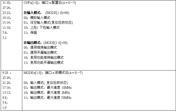
List of GPIO register abbreviations

Each bit of the GPIO port can be configured into multiple modes by software.

During and immediately after reset, the multiplexing function is not enabled and the I/O ports are configured in floating input mode.
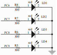
The LED hardware connection is shown in the figure below: A high level lights up the LED.

To successfully light up an LED, the program requires the following steps: (required)
Step 1: Configure the system clock. See STM32F103x RCC register configuration
In addition, the GPIO peripheral clock needs to be turned on.
/* Enable GPIOC clock */
RCC_APB2PeriphClockCmd(RCC_APB2Periph_GPIOC, ENABLE);
void NVIC_Configuration(void)
{
#ifdef VECT_TAB_RAM //VECT_TAB_RAM is not defined in the program, so download the program to Flash
/* Set the Vector Table base location at 0x20000000 */
NVIC_SetVectorTable(NVIC_VectTab_RAM, 0x0);
#else /* VECT_TAB_FLASH */
/* Set the Vector Table base location at 0x08000000 */
NVIC_SetVectorTable(NVIC_VectTab_FLASH, 0x0);
#endif
}
Step 3: Configure the GPIO mode. Input mode or output mode. The focus of this chapter.
void GPIO_Configuration(void)
{
GPIO_InitTypeDef GPIO_InitStructure;
/* Configure PC.06, PC.07, PC.08 and PC.09 as Output push-pull */
GPIO_InitStructure.GPIO_Pin = GPIO_Pin_6 | GPIO_Pin_7 | GPIO_Pin_8 | GPIO_Pin_9;
GPIO_InitStructure.GPIO_Spe ed = GPIO_Speed_50MHz;
GPIO_InitStructure.GPIO_Mode = GPIO_Mode_Out_PP;
GPIO_Init(GPIOC, &GPIO_InitStructure);
}
typedef struct
{
u16 GPIO_Pin; //Which pin
GPIOSpeed_TypeDef GPIO_Speed; //If it is output mode, you also need to set the speed
GPIOMode_TypeDef GPIO_Mode; //Pin type
}GPIO_InitTypeDef;
void GPIO_SetBits(GPIO_TypeDef* GPIOx, u16 GPIO_Pin)
{
/* Check the parameters */
assert_param(IS_GPIO_ALL_PERIPH(GPIOx));
assert_param(IS_GPIO_PIN(GPIO_Pin));
GPIOx->BSRR = GPIO_Pin;
}


v GPIO_ResetBits writes 0 to the specified Pin of the specified Port:
void GPIO_ResetBits(GPIO_TypeDef* GPIOx, u16 GPIO_Pin)
{
/* Check the parameters */
assert_param(IS_GPIO_ALL_PERIPH(GPIOx));
assert_param(IS_GPIO_PIN(GPIO_Pin));
GPIOx->BRR = GPIO_Pin;
}


/* Includes ----------------------------------------------- ------------------*/
#include "stm32f10x_lib.h"
/* Private function prototypes ------------------ ----------------------------------*/
void RCC_Configuration(void);
void NVIC_Configuration(void);
void GPIO_Configuration(void);
void Delay(vu32 nCount);
/****************************************** *************************************
* Function Name: main
* Description: Main program.
* Input : None
* Return : None
********************************************** *************************************/
int main(void)
{
#ifdef DEBUG
debug();
# endif
/* Configure the system clocks */
RCC_Configuration();
/* NVIC Configuration */
NVIC_Configuration();
/* Configure the GPIO ports */
GPIO_Configuration();
/* Infinite loop */
while (1)
{
GPIO_SetBits(GPIOC,GPIO_Pin_6);//Turn on LED1
Delay(1000000);
Delay(1000000);//Turn on for a while so that people can see the exact change of the LED
GPIO_ResetBits(GPIOC,GPIO_Pin_6);//Turn off LED1
GPIO_SetBits(GPIOC,GPIO_Pin_7);//Turn on LED2
Delay(1000000);
Delay(1000000);
GPIO_ResetBits(GPIOC,GPIO_Pin_7);//Turn off LED2
GPIO_SetBits(GPIOC,GPIO_Pin_8);//Turn on LED3
Delay(1000000);
Delay(1000000);
GPIO_ResetBits(GPIOC,GPIO_Pin_8); //Turn off LED3
GPIO_SetBits(GPIOC,GPIO_Pin_9);//Light up LED4
Delay(1000000);
Delay(1000000);
GPIO_ResetBits(GPIOC,GPIO_Pin_9);//Turn off LED4
}
}
/************** *************************************************** ***************
* Function Name : RCC_Configuration
* Description : Configures the different system clocks.
* Input : None
* Return : None
************* *************************************************** ****************/
void RCC_Configuration(void)
{
ErrorStatus HSEStartUpStatus;
/* RCC system reset(for debug purpose) */
RCC_DeInit();
/* Enable HSE */
RCC_HSEConfig( RCC_HSE_ON);
/* Wait till HSE is ready */
HSEStartUpStatus = RCC_WaitForHSEStartUp();
if (HSEStartUpStatus == SUCCESS)
{
/* Enable Prefetch Buffer */
FLASH_PrefetchBufferCmd(FLASH_PrefetchBuffer_Enable);
/* Flash 2 wait state */
FLASH_SetLatency(FLASH_Latency_2);
/* HCLK = SYSCLK */
RCC_HCLKConfig(RCC_SYSCLK_ Div1);
/ * PCLK2 = HCLK */
RCC_PCLK2Config(RCC_HCLK_Div1);
/* PCLK1 = HCLK/2 */
RCC_PCLK1Config(RCC_HCLK_Div2);
/* PLLCLK = 8MHz * 9 = 72 MHz */
RCC_PLLConfig(RCC_PLLSource_HSE_Div1, RCC_PLLMul_9);
/* Enable PLL */
RCC_PLLCmd(ENABLE);
/* Wait till PLL is ready */
while(RCC_GetFlagStatus(RCC_FLAG_PLLRDY) == RESET) {}
/* Select PLL as system clock source */
RCC_SYSCLKConfig(RCC_SYSCLKSource_PLLCLK);
/* Wait till PLL is used as system clock source */
while(RCC_GetSYSCLKSource() != 0x08) {}
}
/* Enable GPIOC clock */
RCC_APB2PeriphClockCmd(RCC_APB2Periph_GPIOC, ENABLE);
}
/********************************************** ******************************************
* Function Name: NVIC_Configuration
* Description: Configures Vector Table base location.
* Input : None
* Return : None
**************************************** ***************************************/
void NVIC_Configuration(void)
{
#ifdef VECT_TAB_RAM
/ * Set the Vector Table base location at 0x20000000 */
NVIC_SetVectorTable(NVIC_VectTab_RAM, 0x0);
#else /* VECT_TAB_FLASH */
/* Set the Vector Table base location at 0x08000000 */
NVIC_SetVectorTable(NVIC_VectTab_FLASH, 0x0);
#endif
}
/****************************************************** ****************************
* Function Name : GPIO_Configuration
* Description : Configures the different GPIO ports.
* Input : None
* Return : None
************************************************ *******************************/
void GPIO_Configuration(void)
{
GPIO_InitTypeDef GPIO_InitStructure;
/* Configure PC.06, PC. 07, PC.08 and PC.09 as Output push-pull */
GPIO_InitStructure.GPIO_Pin = GPIO_Pin_6 | GPIO_Pin_7 | GPIO_Pin_8 | GPIO_Pin_9;
GPIO_InitStructure.GPIO_Speed = GPIO_Speed_50MHz;
GPIO_InitStructure.GPIO_Mode = GPIO_Mode_Out_PP;
GPIO_Init(GPIOC, &GPIO_InitStructure);
}
/********************************************** ******************************************
* Function Name: Delay
* Description: Inserts a delay time .
* Input : nCount: specifies the delay time length.
* Return : None
********************************** *********************************************/
void Delay(vu32 nCount)
{
for(; nCount != 0; nCount--);
}
#ifdef DEBUG
/****************************** ***************************************************
* Function Name: assert_failed
* Description: Reports the name of the source file and the source line number
* where the assert_param error has occurred.
* Input: - file: pointer to the source file name
* - line: assert_param error line source number
* Return: None
** *************************************************** ***************************/
void assert_failed(u8* file, u32 line)
{
/* User can add his own implementation to report the file name and line number,
ex: printf("Wrong parameters value: file %s on line %d\r\n", file, line) */
/* Infinite loop */
while (1)
{
}
}
#endif
How to debug: Set a breakpoint at while (1).
After executing the GPIO_Configuration function, observe the GPIO_CRL and GPIO_CRH registers and you can see:

The mode configuration of each pin is determined by 4 bits in GPIO_CRL or GPIO_CRH. For example, the PC6 pin is determined by the MODE6[1:0] and CNF6[1:0] bits in GPIO_CRL, and the others are determined by analogy.
The GPIO_CRL register is involved, as shown below


After executing GPIO_SetBits(GPIOC,GPIO_Pin_6); //Turn on LED1, you can see: GPIO_ODR's ODR6=1
After executing GPIO_ResetBits(GPIOC,GPIO_Pin_6); //Turn off LED1, you can see: GPIO_ODR's ODR6=0
The same goes for other pins.
Previous article:stm32_exti (including NVIC) configuration and library function explanation
Next article:Further discussion on IAR 4_42A project configuration
Recommended ReadingLatest update time:2024-11-16 16:37


- Popular Resources
- Popular amplifiers
 Professor at Beihang University, dedicated to promoting microcontrollers and embedded systems for over 20 years.
- Innolux's intelligent steer-by-wire solution makes cars smarter and safer
- 8051 MCU - Parity Check
- How to efficiently balance the sensitivity of tactile sensing interfaces
- What should I do if the servo motor shakes? What causes the servo motor to shake quickly?
- 【Brushless Motor】Analysis of three-phase BLDC motor and sharing of two popular development boards
- Midea Industrial Technology's subsidiaries Clou Electronics and Hekang New Energy jointly appeared at the Munich Battery Energy Storage Exhibition and Solar Energy Exhibition
- Guoxin Sichen | Application of ferroelectric memory PB85RS2MC in power battery management, with a capacity of 2M
- Analysis of common faults of frequency converter
- In a head-on competition with Qualcomm, what kind of cockpit products has Intel come up with?
- Dalian Rongke's all-vanadium liquid flow battery energy storage equipment industrialization project has entered the sprint stage before production
- Allegro MicroSystems Introduces Advanced Magnetic and Inductive Position Sensing Solutions at Electronica 2024
- Car key in the left hand, liveness detection radar in the right hand, UWB is imperative for cars!
- After a decade of rapid development, domestic CIS has entered the market
- Aegis Dagger Battery + Thor EM-i Super Hybrid, Geely New Energy has thrown out two "king bombs"
- A brief discussion on functional safety - fault, error, and failure
- In the smart car 2.0 cycle, these core industry chains are facing major opportunities!
- The United States and Japan are developing new batteries. CATL faces challenges? How should China's new energy battery industry respond?
- Murata launches high-precision 6-axis inertial sensor for automobiles
- Ford patents pre-charge alarm to help save costs and respond to emergencies
- New real-time microcontroller system from Texas Instruments enables smarter processing in automotive and industrial applications
- Playing with Zynq Serial 41——[ex60] Image smoothing processing of OV5640 camera
- Thank you + thank you EEWORLD community
- Medical electronics popular data download collection
- Tailing Micro B91 Development Kit --- Testing Power Consumption in BLE Connections
- Application areas of Bluetooth Low Energy
- GaN Power Devices
- PIN diodes for RF circuits explained in detail
- During the fight against the epidemic, we will teach you how to have instruments in your mind without having any in your hands.
- Migrating between TMS320F28004x and TMS320F28002x
- K210 performance test again

 usb_host_device_code
 Transplantation of real-time operating system RT-ThreadSmart on STM32MP1


 京公网安备 11010802033920号