2. Brushless DC motor control system based on LIN bus
LIN bus is a new type of low-cost automobile body bus. It was launched in 1999 by the LIN Association, which was jointly formed by European automobile manufacturers such as Audi, BMW, Daimler2Chrysler, Volvo, Volkswagen, VCT and semiconductor manufacturer Motorola, and has been put into use since 2003.
LIN bus uses serial communication protocol, which has the following characteristics: single host and multiple slaves (no bus arbitration required); low-cost hardware implementation based on ordinary UART/SCI interface, low-cost software or as a pure state machine; slave nodes can achieve self-synchronization without quartz or ceramic resonators; guaranteed signal transmission delay time; low-cost single-line communication medium, communication rate up to 20kb/s. A LIN network consists of 1 master node and no more than 15 slave nodes. All nodes have a slave task, which is divided into receiving tasks and sending tasks, and the master node also has a host task. Communication on the LIN network is always initiated by the host task, which transmits the message frame header, which includes the synchronization interval field, synchronization field and identifier field; the slave task responds to the message, which includes 2, 4 or 8 bytes of data field and check field, and the message frame header and message response constitute a complete message frame.
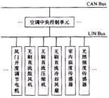
LIN bus is a supplement to CAN bus and is mainly used for body control. The main objects connected to the body network are seats, doors, air conditioners, instrument display and other systems. The block diagram of the fully automatic air conditioning system based on LIN bus is shown in Figure 1. The air conditioning central control unit plays the role of CAN/LIN gateway and LIN master node, and the other units are slave nodes, which are divided into sensor slave nodes and execution slave nodes. The sensor slave node sends environmental status values such as temperature, humidity, and sunlight intensity to the master node. The master node makes a comprehensive decision based on these status values and parameters such as the in-car temperature set by the driver, and conveys control commands to the execution slave node. The execution slave node performs corresponding actions according to the command. Such an air conditioning system effectively realizes the distributed control of nodes, reduces the installation of wiring harnesses on the car, and realizes true full-automatic control, so that the various components of the air conditioning system operate in coordination, so that the indoor temperature reaches and remains at the driver's set value, creating a comfortable indoor environment. Since the brushless DC motor has good speed regulation performance, some execution slave nodes in the air conditioning system use it as a driving component, such as a compressor, blower, cooling fan, etc. These slave nodes and the master node form a brushless DC motor speed closed-loop control based on the LIN bus. The master node gives the motor speed through a decision-making algorithm, and the speed feedback and control algorithm are completed by the slave node. The slave node is the controller that the author wants to design.

Figure 1 Air conditioning system based on LIN bus
3. Controller hardware structure
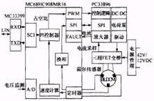
The controller structure block diagram is shown in Figure 2, which includes: power management module, MC68HC908MR16 single-chip control module, PC33896 front-end driver module, three-phase FET full-bridge module, and MC33399LIN physical layer communication module.

Figure 2 Controller structure diagram
The Hall sensor detects the position of the motor rotor, which is a signal with three pulse widths of 180° (electrical angle) and a difference of 120° (electrical angle). The timer input capture unit of the microcontroller captures the change of the position signal, realizes the commutation of the stator winding current, and ensures that the magnetic field generated by the stator and the permanent magnetic field of the rotor maintain an average vertical relationship to generate maximum torque. At the same time, the motor speed can be calculated by the time interval between the two commutations recorded by the timer. The PWM duty cycle is adjusted through the PI algorithm according to the difference between the target speed and the calculated speed, thereby controlling the motor speed. The motor's target speed, start/stop, forward/reverse and other information come from the message frame of the LIN bus.
3.1 Power Management Module
The electrical load inside modern cars is increasing. In the future, cars will use 42V power supply instead of the existing 12V power supply. However, there are still many problems to be solved to fully realize this transformation. Currently, 42V/12V dual power supply is mainly used as a transitional solution. The controller designed by the author takes this development trend into consideration. In 12V motor applications, the controller uses a single 12V power supply; in 42V motor applications, the controller uses a 42V/12V dual power supply. At the same time, the power management module contains a 12V/5V power supply regulator chip LT1211.
3.2 MCU control module
The single-chip control module is based on the MC68HC908MR16 single-chip microcomputer, which is an 8-bit single-chip microcomputer specially used for motor control. The operating temperature range reaches -40~105℃, which is fully adapted to the working environment in the car. The chip has a 12-bit, 6-channel PWM module that generates 6 PWM logic signals (which can be set to 6 independent channels or 3 pairs of complementary signals); the three channels 0, 1, and 2 of timer A are used to capture changes in position sensor signals, and channel 3 is responsible for recording the moment when the position signal of channel 2 changes; the 10-bit A/D converter has a conversion time of 16-17μs and can quickly complete the battery voltage monitoring task; the error signal input is used to generate an interrupt in the event of overcurrent or overheating, thereby blocking the PWM output; the unique fast 8-bit multiplication and 16-bit division instructions give it a higher computing power and can complete more complex control algorithms; 768B on-chip RAM and 16kB on-chip Flash memory have online programming capabilities and confidentiality functions; system protection features, including watchdog reset and low-voltage reset, enhance the stability and reliability of the program.
3.3 Front drive module
The core of the pre-driver module is PC33896, which is a newly launched three-phase FET pre-driver dedicated to automotive electronic 42V/12V systems. The chip contains DC/DC step-down circuit, current sampling amplifier, SPI communication port and various protection circuits. PC33896 directly receives 6 PWM logic signals from the microcontroller and converts them into drive signals for driving 6 FET gates. If the power supply voltage of the automotive system is the new 42V power system, the DC/DC in the chip will reduce it to about 15V for FET gate circuit drive, saving the power dissipated by turning on and off the FET; if the power supply voltage of the automotive power supply adopts the current 12V power system, in some cases the power supply voltage will not be enough to drive the FET gate. At this time, the charge pump circuit will increase it to at least 10V to ensure the normal drive of the FET. The internal current sampling amplifier is used to measure the DC bus current. The microcontroller can send instructions through the SPI port to configure PC33896 (such as whether the DC/DC and charge pump work, the amplification factor of the current amplifier, etc.) and diagnose its faults.
3.4 LIN physical layer communication module
MC33399 is a LIN transceiver chip for automotive electronic applications. It and the SCI port of the microcontroller form the physical basis of LIN communication. It has two working modes: normal and sleep. The wake-up frame on the bus can wake it up from sleep mode.
4. Controller software design
Because the built-in hardware modules of the MCU and PC33896 are powerful, the MCU has enough resources to complete more complex control strategies, thus greatly improving the performance of the controller.
4.1 Main program structure
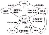
The system program adopts a foreground and background structure. The foreground is the interrupt level, and the background is the task level. The task level consists of an infinite loop and a LIN communication service program. The infinite loop contains a finite state machine and a 10ms service program. The finite state machine is shown in Figure 3. The system enters the infinite loop after powering on and completing the initialization task. Once an SCI reception interrupt occurs, the interrupt service program determines whether the received is a synchronous interval field. If it is a synchronous interval field, the program does not return to the infinite loop when exiting the interrupt service, but enters the LIN communication service program to receive and process the message frame. After completing the communication service, the program returns to the infinite loop. According to the received message frame, the finite state machine switches to the corresponding state. To protect the motor, the transition between the forward state and the reverse state in the figure is forced to go through the intermediate stop state transition. When an error event such as overcurrent or low voltage occurs, the controller enters the error state, which turns off all PWM outputs and records the error code. After the controller receives the sleep frame of the bus, it enters the sleep state, and the wake-up signal of the bus will reactivate the controller. In the forward or reverse state, the 10ms service program in the dead loop is executed every 10ms to complete tasks such as motor speed calculation, PI control algorithm, and battery voltage reading.

Figure 3 Main program finite state machine
4.2 Customization of LIN communication message frame
LIN bus is a master-slave communication mode. The customization of message frames is done during the overall design of LIN network software. The brushless DC motor controller in this article is a slave node on the bus. The message frames it responds to are shown in Table 1. The identifier "0x3C" is a download command frame, which is used by the master node to broadcast commands and data to all slave nodes. The first data byte is "00" is a sleep frame. The identifier "0x3D" is an upload command frame, which triggers a slave node (addressed by a priority download frame) to upload data to the host. The identifier "0x20" is a brushless motor control frame, which is used by the controller to receive control information from the master node. The first data byte is "01" to request the motor to rotate forward, "02" is reverse, and "04" is to stop. The third and fourth data bytes are the given values of the motor speed. The identifier "0x21" is a motor status frame, which is used by the controller to transmit information to the master node. The first and second data bytes are the actual speed of the motor, and the third and fourth bytes represent the battery voltage.
Table 1 LIN message frame responded by the controller

4.3 Interrupt Service Routine in Software
4.3.1 Timer A0, A1, A2 input capture interrupt (inputcap2ture ISR1)
When timers A0, A1, and A2 detect a transition edge in the position signal, an input capture interrupt ISR1 is triggered. In the interrupt program, the current levels of the three pins are read and combined with the values read in the previous interrupt to query the commutation table to complete the commutation.
4.3.2 Timer A3 input capture interrupt (inputcapture ISR2)
When timer A3 detects a rising edge jump in the position signal of channel A2, it triggers input capture interrupt ISR2. The interrupt program reads the current value of the capture register of channel A3 of timer, combines the value read in the previous interrupt and the number of overflows of timer A, calculates the count of the high-frequency clock pulses of timer A within a position pulse cycle, and the result is used for speed calculation.
4.3.3 Timer B Overflow Interrupt (TIMERB ISR)
Timer B overflows and interrupts once every 10ms. The flag timerflag is set in the interrupt program, so that the 10ms service program in the main program's dead loop can be executed.
The interrupts of timer A3 and timer B are allowed to be turned off in the LIN communication service program, while the commutation interrupt is retained, thus ensuring the reliability of communication and the stable operation of the motor.
5. Test results
The designed controller is used to test a brushless DC motor (whose specifications are equivalent to the brushless motor for driving the air conditioner blower of a passenger car with a rated voltage of 48V and a rated power of 150W). The test diagram is shown in Figure 4.

Figure 4 Test diagram
The controller in Figure 4 is powered by 42V/12V dual voltage. The master node of the LIN bus is simulated by a PC, which is connected to the LIN bus through an RS232 serial port via a RS232 to LIN interface card PC card. The LIN communication software is developed using the Labview interface environment.
The actual operation results show that the motor can start and brake quickly, and accurately and timely track the given speed of the main node. The controller runs stably and reliably and can meet the requirements of real-time control.
6 Conclusion
The brushless DC motor controller based on LIN bus designed by the author has a simple hardware circuit structure, is compatible with the 42V power supply system of future cars, and has a high cost performance. In addition, since LIN bus is an open protocol, the controller is not only suitable for the automotive electronics field, but also can be used in other fields such as industrial control and home appliances.
Previous article:Design of driving recorder system based on MC9S12XD
Next article:Design of a fast charging system for electric vehicles
 Professor at Beihang University, dedicated to promoting microcontrollers and embedded systems for over 20 years.
- LED chemical incompatibility test to see which chemicals LEDs can be used with
- Application of ARM9 hardware coprocessor on WinCE embedded motherboard
- What are the key points for selecting rotor flowmeter?
- LM317 high power charger circuit
- A brief analysis of Embest's application and development of embedded medical devices
- Single-phase RC protection circuit
- stm32 PVD programmable voltage monitor
- Introduction and measurement of edge trigger and level trigger of 51 single chip microcomputer
- Improved design of Linux system software shell protection technology
- What to do if the ABB robot protection device stops
- Innovation is not limited to Meizhi, Welling will appear at the 2024 China Home Appliance Technology Conference
- Innovation is not limited to Meizhi, Welling will appear at the 2024 China Home Appliance Technology Conference
- Huawei's Strategic Department Director Gai Gang: The cumulative installed base of open source Euler operating system exceeds 10 million sets
- Download from the Internet--ARM Getting Started Notes
- Learn ARM development(22)
- Learn ARM development(21)
- Learn ARM development(20)
- Learn ARM development(19)
- Learn ARM development(14)
- Learn ARM development(15)
- Board burning problem
- X-NUCLEO-IKS01A3 driver for Arduino
- Nexperia Award-winning Live Broadcast: Introduction and Application of Automotive Power MOSFET and GaN Devices in Electric Vehicles
- Nordic Bluetooth sensor monitors guitar temperature and humidity
- EEWORLD University Hall - Altium Designer 22 Electronic Design Introduction Practice 56 Lectures
- ztool cannot connect
- IEEE Spectrum Top Programming Language Rankings April 2022
- ADS1278 data acquisition chip data distortion problem
- Could you please advise what is wrong with this circuit?
- USB power supply and DC power supply issues

 Computer Vision Applications in Autonomous Vehicles: Methods, Challenges, and Future Directions


 京公网安备 11010802033920号