1. Basic reset circuit 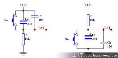 Figure 1 RC reset circuit The reset circuit shown in Figure 2 adds a diode, which makes the capacitor discharge quickly when the power supply voltage drops instantly. A certain width of power burrs can also reset the system reliably. The lower half of the input-output characteristic diagram of the reset circuit shown in Figure 3 is its characteristics, which can be compared with the upper half to add the effect of the discharge circuit.
 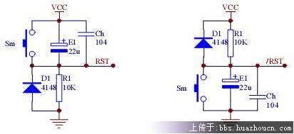 Figure 2 The RC reset circuit with a discharge loop uses a comparison circuit, which can not only solve the problem of system instability caused by power glitches, but also can reliably reset the system when the power supply drops slowly. Figure 4 is an example. When VCC x (R1/(R1+R2)) = 0.7V, Q1 is cut off to reset the system. The amplification effect of Q1 can also improve the load characteristics of the circuit, but the transition threshold voltage Vt is affected by VCC, which is a prominent disadvantage of this circuit. The use of a voltage regulator diode can make Vt basically unaffected by VCC. See Figure 5. When VCC is lower than Vt (Vz+0.7V), the circuit resets the system.
 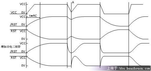 Figure 3 Input-output characteristics of the RC reset circuit
 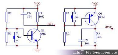 Figure 4 Reset circuit with voltage monitoring function
 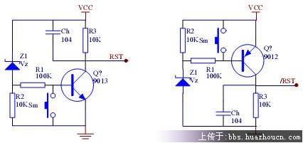 Figure 5 Stable threshold voltage
 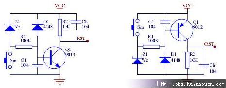 Figure 6 Practical reset monitoring circuit
Reference address:Reset circuit of 51 single chip microcomputer
 Figure 1 RC reset circuit The reset circuit shown in Figure 2 adds a diode, which makes the capacitor discharge quickly when the power supply voltage drops instantly. A certain width of power burrs can also reset the system reliably. The lower half of the input-output characteristic diagram of the reset circuit shown in Figure 3 is its characteristics, which can be compared with the upper half to add the effect of the discharge circuit.
  Figure 2 The RC reset circuit with a discharge loop uses a comparison circuit, which can not only solve the problem of system instability caused by power glitches, but also can reliably reset the system when the power supply drops slowly. Figure 4 is an example. When VCC x (R1/(R1+R2)) = 0.7V, Q1 is cut off to reset the system. The amplification effect of Q1 can also improve the load characteristics of the circuit, but the transition threshold voltage Vt is affected by VCC, which is a prominent disadvantage of this circuit. The use of a voltage regulator diode can make Vt basically unaffected by VCC. See Figure 5. When VCC is lower than Vt (Vz+0.7V), the circuit resets the system.
  Figure 3 Input-output characteristics of the RC reset circuit
  Figure 4 Reset circuit with voltage monitoring function
  Figure 5 Stable threshold voltage
  Figure 6 Practical reset monitoring circuit
Previous article:MCU RAM usage
Next article:c8051f330 series microcontroller AD conversion
- Popular Resources
- Popular amplifiers
Recommended Content
Latest Microcontroller Articles
- Learn ARM development(16)
- Learn ARM development(17)
- Learn ARM development(18)
- Embedded system debugging simulation tool
- A small question that has been bothering me recently has finally been solved~~
- Learn ARM development (1)
- Learn ARM development (2)
- Learn ARM development (4)
- Learn ARM development (6)
He Limin Column
Microcontroller and Embedded Systems Bible
 Professor at Beihang University, dedicated to promoting microcontrollers and embedded systems for over 20 years.
MoreSelected Circuit Diagrams
MorePopular Articles
- LED chemical incompatibility test to see which chemicals LEDs can be used with
- Application of ARM9 hardware coprocessor on WinCE embedded motherboard
- What are the key points for selecting rotor flowmeter?
- LM317 high power charger circuit
- A brief analysis of Embest's application and development of embedded medical devices
- Single-phase RC protection circuit
- stm32 PVD programmable voltage monitor
- Introduction and measurement of edge trigger and level trigger of 51 single chip microcomputer
- Improved design of Linux system software shell protection technology
- What to do if the ABB robot protection device stops
MoreDaily News
- Analysis of the application of several common contact parts in high-voltage connectors of new energy vehicles
- Wiring harness durability test and contact voltage drop test method
- From probes to power supplies, Tektronix is leading the way in comprehensive innovation in power electronics testing
- From probes to power supplies, Tektronix is leading the way in comprehensive innovation in power electronics testing
- Sn-doped CuO nanostructure-based ethanol gas sensor for real-time drunk driving detection in vehicles
- Design considerations for automotive battery wiring harness
- Do you know all the various motors commonly used in automotive electronics?
- What are the functions of the Internet of Vehicles? What are the uses and benefits of the Internet of Vehicles?
- Power Inverter - A critical safety system for electric vehicles
- Analysis of the information security mechanism of AUTOSAR, the automotive embedded software framework
Guess you like
- Schottky diode voltage drop test
- Oscilloscope is fun, it’s more than just waveform display!
- Feiling FETT507-C core board 4-way AHD camera implementation solution
- DSP ccs2 C5000 compiles SUBC instruction to implement division
- Push-button start system power supply circuit
- Tell us what you think about 996
- Amplification issues of differential amplifiers
- New design approach improves smart meter performance
- How to view NPU clock power configuration and information for Allwinner V853 chip?
- USB PD fast charging communication principle

 5962-01-032-5946


 京公网安备 11010802033920号