| Logic and Instructions
ANL A,Rn; The values in A and Rn are bitwise ANDed, and the result is sent to A ANL A,direct; The values in A and direct are bitwise ANDed, and the result is sent to A ANL A,@Ri; A and the value in the indirect addressing unit @Ri are bitwise ANDed, and the result is sent to A ANL A,#data; A and the immediate data are bitwise ANDed, and the result is sent to A ANL direct,A; the value in direct and the value in A are bitwise ANDed, and the result is sent to direct ANL direct, #data; The value in direct is bitwise ANDed with the immediate data, and the result is sent to direct. The key to these instructions is to know what logical AND is. Here logical AND refers to bitwise AND. |
| For example: 71H and 56H are ANDed together, and the two numbers are written in binary form:
(71H) 01110001 (56H) 00100110 The result is 00100000, which is 20H. From the above formula, we can see that if one of the two values involved in the operation is 0, the result of that bit will be 0. If both are 1, the result will be 1. Once you understand the logical AND operation rules, the result will come out naturally. See the comments after each instruction |
| Let’s look at some more examples.
MOV A,#45H ;(A)=45H MOV R1,#25H ;(R1)=25H MOV 25H,#79H ;(25H)=79H ANL A,@R1; 45H and 79H are bitwise ANDed, and the result is sent to A, which is 41H (A) = 41H ANL 25H,#15H; The value in 25H (79H) and 15H result in (25H) = 11H) ANL 25H,A; The value in 25H (11H) and the value in A (41H) are ANDed, and the result is (25H) = 11H After knowing the function of logical and instruction, the function of logical or and logical exclusive or is very simple. Logical or is bitwise "or", that is, all "1" is 1, all "0" is 0. Example: 10011000 or 01100001 Result 11111001 XOR is a bit-wise XOR, where the same is "0" and different is "1". Example: 10011000 XOR 01100001 Result 11111001 |
| All the OR instructions replace the ANL in the AND instruction with ORL, and the XOR instruction replaces ANL with XRL.
Or the command: ORL A,Rn; The values in A and Rn are bitwise ORed, and the result is sent to A ORL A,direct; A and the value in the indirect addressing unit @Ri are bitwise ORed, and the result is sent to A ORL A,#data; A and the value in direct are bitwise ORed, and the result is sent to A ORL A,@Ri; A and data are bitwise ORed, and the result is sent to A ORL direct,A; the value in direct and the value in A are bitwise ORed, and the result is sent to direct ORL direct,#data; The value in direct and the immediate data are bitwise ORed together, and the result is sent to direct. XOR instruction: XRL A,Rn; The values in A and Rn are bitwise XORed, and the result is sent to A XRL A,direct; The values in A and direct are bitwise XORed, and the result is sent to A. XRL A,@Ri; A and the value in the indirect addressing unit @Ri are bitwise XORed, and the result is sent to A XRL A,#data; A and immediate data are bitwise XORed, and the result is sent to A XRL direct,A ; The value in direct and the value in A are bitwise XORed, and the result is sent to direct XRL direct,#data; The value in direct and the immediate data are bitwise XORed, and the result is sent to direct. |
| practise:
MOV A,#24H MOV R0,#37H ORL A,R0 XRL A,#29H MOV 35H,#10H ORL 35H,#29H MOV R0,#35H ANL A,@R0 |
| 4. Control transfer instructions Unconditional transfer instructions Short transfer instructions AJMP addr11 Long transfer instructions LJMP addr16 Relative jump instructions SJMP rel |
| If we analyze the three instructions above carefully, we will find that they are quite different. But when you are a beginner, you can ignore them and understand them all as: JMP label, that is, jump to a label. In fact, we have already come into contact with the LJMP label in the previous routines, and we also know how to use it. The same is true for AJMP and SJMP. So what is the difference between them? It is that the jump range is different. For example, in a long jump, LJMP can jump 64K at a time (of course, it doesn't matter if it is closer). However, AJMP can only jump 2K at most, and SJMP can only jump 256 at most. In principle, all places where SJMP or AJMP is used can be replaced by LJMP. Therefore, when you are a beginner, you can use LJMP when you need to jump, except for one occasion. What occasion? First, let's understand AJMP. AJMP is a two-byte instruction, which means that this instruction itself occupies two units of the memory (ROM). LJMP is a three-byte instruction, which means that this instruction occupies three units of the memory (ROM). Below is the fourth jump instruction. |
| 4. Indirect transfer instructions
JMP @A+DPTR This instruction is also used to jump. Where does it jump to? This cannot be simply determined by the label. Let's start with a practical example. MOV DPTR,#TAB ; send the address represented by TAB to DPTR MOV A,R0; Get data from R0 (see the following description for details) MOV B,#2 MUL A,B; multiply the value in A by 2 (see the following description for details) JMP A,@A+DPTR ; Jump TAB: AJMP S1 ; Jump to table AJMP S2 AJMP S3 . . . |
 |
 |
|
figure 2
|
 |
|
image 3
|
| Application background: In the development of single-chip microcomputers, keyboards are often used, see the 9-key keyboard above. Our requirement is: when the function keys A…G are pressed, different functions are completed. If this is expressed in programming language, it means: pressing different keys will execute different program segments to complete different functions. How to achieve this?
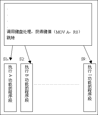
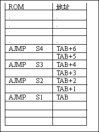
See Figure 2. The previous program reads in the key values. For example, after pressing the ''''A''' key, the key value is 0, and after pressing the ''''B'''' key, the value is ''''1'''', and so on. Then it jumps according to different values. For example, if the key value is 0, it jumps to S1 for execution, and if it is 1, it jumps to S2 for execution. . . . How to implement this function? Let's start from the bottom of the program. There are several AJMP statements. These AJMP statements are finally stored in the memory like this (see Figure 3). That is, each AJMP statement occupies two memory spaces and is stored continuously. The address stored in AJMP S1 is TAB. We don't need to know what TAB is. We can leave it to the assembler to calculate. |
| Let's look at the execution process of this program: After the first sentence MOV DPTR, #TAB is executed, the value in DPTR is TAB. The second sentence is MOV A, R0. We assume that R0 is the key value obtained by the key processing program. For example, if the A key is pressed, the value in R0 is 0, and if the B key is pressed, the value in R0 is 1. And so on. Now let's assume that the B key is pressed. After executing the second instruction, the value in A is 1. And according to our analysis, after pressing B, the S2 program should be executed. Let's see if this is the case? The third and fourth instructions multiply the value in A by 2, that is, after executing the fourth instruction, the value in A is 2. Next, JMP @A+DPTR is executed. Now the value in DPTR is TAB, and after A+DPTR is TAB+2. Therefore, after executing this sentence, it will jump to the address TAB+2 and continue to execute. Let's see what is placed in the address TAB+2? It is the instruction AJMP S2. Therefore, the AJMP S2 instruction is executed immediately, and the program will jump to S2 and continue executing, which meets our requirements.
Please analyze the situation after pressing the keys "A", "C", "D", etc. In this way, we use JMP @A+DPTR to realize the requirement of jumping to the corresponding program segment to execute when pressing a key. Let me ask you another question, why do we need to multiply the key value by 2? If all the instructions below the routine are replaced with LJMP, that is: LJMP S1, LJMP S2... Can this program still be executed correctly? If not, how should it be modified? |
Previous article:Ordinary MCU Teaching——Lecture 13 MCU Instructions (VII)
Next article:Ordinary MCU Teaching——Lecture 11 MCU Instructions (V)
- Popular Resources
- Popular amplifiers
 Professor at Beihang University, dedicated to promoting microcontrollers and embedded systems for over 20 years.
- LED chemical incompatibility test to see which chemicals LEDs can be used with
- Application of ARM9 hardware coprocessor on WinCE embedded motherboard
- What are the key points for selecting rotor flowmeter?
- LM317 high power charger circuit
- A brief analysis of Embest's application and development of embedded medical devices
- Single-phase RC protection circuit
- stm32 PVD programmable voltage monitor
- Introduction and measurement of edge trigger and level trigger of 51 single chip microcomputer
- Improved design of Linux system software shell protection technology
- What to do if the ABB robot protection device stops
- Huawei's Strategic Department Director Gai Gang: The cumulative installed base of open source Euler operating system exceeds 10 million sets
- Download from the Internet--ARM Getting Started Notes
- Learn ARM development(22)
- Learn ARM development(21)
- Learn ARM development(20)
- Learn ARM development(19)
- Learn ARM development(14)
- Learn ARM development(15)
- Analysis of the application of several common contact parts in high-voltage connectors of new energy vehicles
- Wiring harness durability test and contact voltage drop test method
- TMS320 C6000 series DSP CCS5.5 simulation debugging
- Learning 3D visualization scene hierarchy from scratch (2)
- [Sipeed LicheeRV 86 Panel Review] V. The system image was finally created successfully, but...
- [Atria AT32WB415 Series Bluetooth BLE 5.0 MCU] WDT Watchdog Analysis and Application
- C program about low power consumption msp430PID control motor speed
- My Journey of MCU Development (Part 3)
- Design of Programmable SOC System Based on AXI4
- Universal control board based on 3U PXIe ZU11EG
- Real-time control technologies meet the demands of real-time industrial communications - Part 2
- No more looking down! ADAS gives rise to head-up display technology

 CLC407SMD


 京公网安备 11010802033920号