LED Principle and Control Technology
1. What is LED?
LED is the abbreviation of light-emitting diode. In the PN junction of certain semiconductor materials, when the injected minority carriers recombine with the majority carriers, the excess energy will be released in the form of light, thereby directly converting electrical energy into light energy. When a reverse voltage is applied to the PN junction, it is difficult for minority carriers to be injected, so no light is emitted. This type of diode made using the principle of injection electroluminescence is called a light-emitting diode, commonly known as LED.
2. Characteristics and advantages of LED electronic display screen
As a modern electronic media, LED electronic display screen is irreplaceable by any other media due to its flexible display area (dividable and arbitrary assembly), high brightness, long life, large capacity, digitalization and real-time performance. LED electronic display screen makes full use of modern information technology to integrate and perfectly combine sound, light, electricity, machinery and other disciplines, and is a high-tech information publishing terminal product that integrates video, animation, subtitles and pictures.
LED
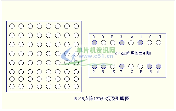
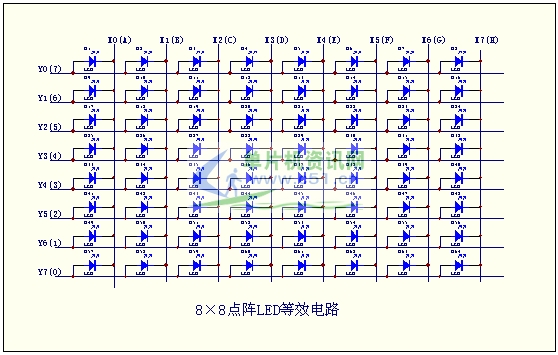
Figure ( 1 ) shows the appearance and pin diagram of the 8 × 8 dot matrix LED . Its equivalent circuit is shown in Figure ( 2 ). As long as the corresponding X and Y axes are forward biased, the LED can be lit. For example, if you want to light up the upper left corner LED , then Y0=1 , X0=0 . When applied, the current limiting resistor can be placed on the X axis or Y axis.

Figure ( 1 ) 8 × 8 dot matrix LED appearance and pin diagram [page]

Figure ( 2 ) 8 × 8 dot matrix LED equivalent circuit

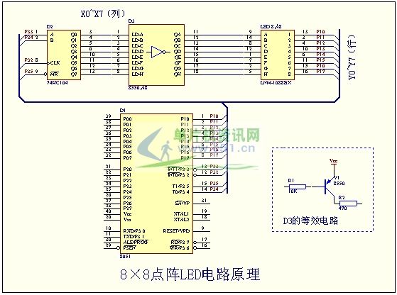
Figure ( 3 ) 8 × 8 dot matrix LED circuit principle
Introduction to dot matrix LED scanning method
Dot matrix LED generally adopts scanning display, and its actual application can be divided into three ways:
(1) Point scanning;
(2) Line scanning;
(3) Column scanning.
If the first method is used, the scanning frequency must be greater than 16 × 64 = 1024Hz and the period must be less than 1ms.
Yes. If the second and third methods are used, the frequency must be greater than 16 × 8 = 128Hz , and the period must be less than 7.8ms to meet the visual retention requirements. In addition, when driving one column or one row ( 8 LEDs ) at a time , an external drive circuit is required to increase the current, otherwise the LED brightness will be insufficient. As shown in Figure 3 .
The following is a routine that uses the P1 port to control scanning and the 74HC164 to control the display output, so that the 8 × 8 dot matrix LED displays an “×”. As shown in Figure ( 3 ). [page]
CLK EQU P3.2
DINA EQU P3.3
DINB EQU P3.4
CLEAR EQU P3.5
ORG 0000H
AJMP MAIN
ORG 0100H
MAIN:
MOV SP,#70H ; Set stack pointer
MOV 50H,#07EH ; Set the column data to be sent (Y0~Y7)
MOV 51H,#0BDH
MOV 52H,#0DBH
MOV 53H,#0E7H
MOV 54H,#0E7H
MOV 55H,#0DBH
MOV 56H,#0BDH
MOV 57H,#07EH
CLR CLEAR ; Initialize I/O port
SETB CLK
SETB DINA
SETB DINB
SETB CLEAR
main loop:
mov r6,#8h ; Set the number of scans
mov dptr,#09000h ; read scan port data
MOV R1,#50H ; Specify column data pointer
flashcy:
MOV A,@R1 ; read column data
MOV R0,A
INC R1 ; column data pointer plus 1
CLR A
MOVC A,@A+DPTR
MOV P1,#0FFH
LCALL SENDTO
MOV P1,A
INC DPTR
LCALL DELAY
DJNZ R6,flashcy
SJMP MAINLOOP
sendto: ; Send data subroutine
PUSH ACC
CLR CLK
BROADCAST TIME:
MOV R7,#08H
MOV A,R0
CLR C
SENDCY:
RRC A
MOV DINA,C
SETB CLK
CLRCLK
DJNZ R7,SENDCY
POP ACC
RIGHT
DELAY: MOV R7,#01 ; Delay subroutine
DELAY0: MOV R4,#17
DELAY1: MOV R3,#28
DJNZ R3,$
DJNZ R4,DELAY1
DJNZ R7,DELAY0
RIGHT
ORG 09000H
DB 0FEH, 0FDH, 0FBH, 0F7H, 0EFH, 0DFH, 0BFH, 07FH ; X0~X7 ( column scan )
end
Previous article:Design of a bell ringer based on a single chip microcomputer
Next article:Design of single chip remote light control box
Recommended ReadingLatest update time:2024-11-16 16:51


- Popular Resources
- Popular amplifiers
-
 Network Operating System (Edited by Li Zhixi)
 -
 Microgrid Stability Analysis and Control Microgrid Modeling Stability Analysis and Control to Improve Power Distribution and Power Flow Control (
 -
 Wireless Sensor Network Technology and Applications (Edited by Mou Si, Yin Hong, and Su Xing)
 -
 MATLAB and FPGA implementation of wireless communication
 Professor at Beihang University, dedicated to promoting microcontrollers and embedded systems for over 20 years.
- Innolux's intelligent steer-by-wire solution makes cars smarter and safer
- 8051 MCU - Parity Check
- How to efficiently balance the sensitivity of tactile sensing interfaces
- What should I do if the servo motor shakes? What causes the servo motor to shake quickly?
- 【Brushless Motor】Analysis of three-phase BLDC motor and sharing of two popular development boards
- Midea Industrial Technology's subsidiaries Clou Electronics and Hekang New Energy jointly appeared at the Munich Battery Energy Storage Exhibition and Solar Energy Exhibition
- Guoxin Sichen | Application of ferroelectric memory PB85RS2MC in power battery management, with a capacity of 2M
- Analysis of common faults of frequency converter
- In a head-on competition with Qualcomm, what kind of cockpit products has Intel come up with?
- Dalian Rongke's all-vanadium liquid flow battery energy storage equipment industrialization project has entered the sprint stage before production
- Allegro MicroSystems Introduces Advanced Magnetic and Inductive Position Sensing Solutions at Electronica 2024
- Car key in the left hand, liveness detection radar in the right hand, UWB is imperative for cars!
- After a decade of rapid development, domestic CIS has entered the market
- Aegis Dagger Battery + Thor EM-i Super Hybrid, Geely New Energy has thrown out two "king bombs"
- A brief discussion on functional safety - fault, error, and failure
- In the smart car 2.0 cycle, these core industry chains are facing major opportunities!
- The United States and Japan are developing new batteries. CATL faces challenges? How should China's new energy battery industry respond?
- Murata launches high-precision 6-axis inertial sensor for automobiles
- Ford patents pre-charge alarm to help save costs and respond to emergencies
- New real-time microcontroller system from Texas Instruments enables smarter processing in automotive and industrial applications
- I have a question about the voltage regulator.
- GigaDevice GD32E231 DIY Competition Finalists
- [AB32VG1 Development Board Review] Button Control LED and Fan
- Writing cmd files in CCS
- Switching Power Supply Interest Group 17th Task
- The live broadcast has ended [Microchip Embedded Security Solutions | RISC-V Safe Place]
- EEWORLD University Hall----Live Replay: Application of MSP430 in Stepper Motor
- Recruiting mbse part-time training teachers
- [NXP Rapid IoT Review] Data Cloud Synchronization
- I am offering a reward to find a DSP expert with sufficient skills to be my mentor. It will be paid.

 Network Operating System (Edited by Li Zhixi)


 京公网安备 11010802033920号