At present, digital electrical measurement and protection devices based on single-chip microcomputers have become the mainstream form. Direct sampling of AC signals has also become a common method. Fast Fourier algorithm is the main algorithm, while the least squares algorithm has a large amount of calculation. Especially when the processing power of single-chip microcomputers is limited, it is difficult to ensure both real-time performance and calculation speed without careful design and program optimization.
By reducing the number of sampling times, using a filter that fits four sampling points per week and a set of optimization measures, the algorithm's calculation speed is greatly improved, making it capable of real-time measurement of power frequency vectors, and thus can be used in multiple aspects such as overcurrent, quick disconnection, and directional protection. This paper analyzes the vector phase relationship in the filter and gives an example of two-wire power calculation based on this. This method has been verified by practical applications.
1 Construction of Least Squares Filter
According to the research results of literature [1-3], for each signal, the input voltage function can be expressed as:

In general measurement and protection applications, only the fundamental wave component is of concern. To reduce the amount of calculation, the number of samplings should be minimized. According to the sampling theorem, the number of discrete samplings of a sine function is at least 3 times per cycle. For convenience, the number of samplings per cycle is set to 4, that is, the sampling period is 5ms. Then formula (1) can only contain DC and power frequency components. Expand the DC component according to the Taylor series and take the first two terms, then formula (1) becomes:

Among them, P0 is the DC component value, P1 is the peak-to-peak value of the fundamental wave, and θ1 is the phase angle of the fundamental wave component relative to the zero point at the sampling time.
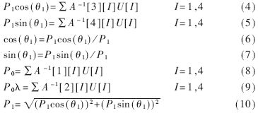
If the last four consecutive sampling values are used as samples, four sampling equations can be obtained. If P0, -P0λ, P1cos(θ1)P1sin(θ1) are used as unknown variables to be measured, the four sampling equations can be expressed as the following matrix:

If we use A to represent the coefficient matrix, X to represent the unknown parameter vector, and U to represent the sample value, then:

Where A-1 represents the inverse matrix of A, that is, the least squares filter of vector X. According to the literature [3], this filter is:

therefore,

In practical applications, in order to reduce the calculation error caused by the time delay caused by the sequential sampling of the single chip, the hardware circuit should have a synchronous sampling function. Its function is to keep all electrical signals separately at the sampling moment.
2 Relationship of instantaneous phasors in digital filters
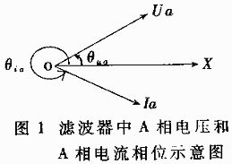
If ua, ub, uc are used to represent the three-phase voltage phasors, Ua, Ub, Uc are used to represent their effective values, and the initial phase angles are θua, θub, θuc respectively; ia, ib, ic are used to represent the three-phase current phasors, Ia, Ib, Ic are used to represent their effective values, and the initial phase angles are θia, θib, θic respectively. Then equation (4) is the projection of the corresponding phasor on the X-axis, that is, the real part of the vector; equation (5) is the projection of the phasor on the Y-axis, that is, the imaginary part of the vector. θ1 in equations (4) and (5) is the phase angle of the above phasor relative to the initial moment of the 20ms time window. [page]
FIG. 1 shows the phase relationship between the A-phase voltage and the A-phase current, and the others are similar.

The phase relationship of the above phasors is the basis for further phasor operations.
3 Two-wire power calculation
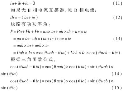
At present, the power measurement of high-voltage lines generally adopts three-phase voltage and two sets of current, that is, the two-wire power meter method. The active power and reactive power of the line can be measured using equations (4), (5), (6), (7) and (10). The specific process is as follows:
The two-wire system assumes that the three-phase current is balanced, that is:

Among them, uab is the line voltage between phase A and phase B; ucb is the line voltage between phase C and phase B.
Substituting the results of (6) and (7) into (14), (15) and (13), the active power of the three-phase balanced line can be measured.
If the input voltage is phase voltage, then:

After expanding the cosine function in the above formula, substitute the corresponding results of formulas (6) and (7) into it.
The calculation of reactive power only requires replacing the cosine operation in equations (14), (15) and (16) with the corresponding sine operation.
4 Optimization measures based on MCU application
From the current market situation, although the performance of single-chip microcomputers is constantly improving, such as INTEL single-chip microcomputers from 8-bit, 16-bit to 32-bit, the products with the best performance are not really widely adopted. From the perspective of practical applications, sometimes we have to face a limited objective reality. For this application, the following measures can greatly improve the calculation speed of the program.
4.1 Convert floating point operations to integer operations
For equations (4) to (10), using C or PL/M high-level language for floating-point operations is convenient and accurate. However, compared with integer operations, floating-point operations are much slower. Therefore, in order to increase the calculation speed, integer operations should be used as much as possible. From the perspective of engineering practice, the result after A/D conversion is generally a double-byte integer, which can be directly operated with the least squares filter with a 10-bit magnification. Then equation (4) becomes:

Equations (17) and (18) only have 6 4-byte long integer multiplications and 4 additions. Even for a 12-bit A/D, the calculation results of equations (17) and (18) will not overflow. Since the filter is an integer when it is expanded by 10 times, there is no rounding, so there is no additional error in the calculation process.
4.2 Fast square root method
From equations (4) to (10), it can be seen that equation (10) consumes the most time, that is, calculating the square root operation to obtain the peak-to-peak value of the fundamental wave.
If the square root function provided by the standard floating point library is used directly, the 16MHz 80196KC requires about 3ms. If the integer table lookup method in reference [4] or the binary search method with an accuracy of 1% provided in reference [5] is used, the time required to find the root under the same conditions is generally between 100 and 300μs, and the calculation speed is increased by more than 10 times.
The least squares filter with four sampling points per cycle proposed in this paper can realize real-time phasor measurement of power frequency signals in general single-chip microcomputers. After further optimization of the algorithm, it can make real-time reflection of multi-channel signals within a time window of one cycle, meeting the technical requirements of general protection. The algorithm can also realize other protection and measurement functions.
References
1 Yang Qixun. Fundamentals of Microcomputer Relay Protection. Beijing: Water Conservancy and Electric Power Press
2 Ding Weidong. Error analysis of the constant least squares filter in real-time processing of power grid AC signals. Shandong Electric Power Technology, 1995; (2)
3 Ding Weidong. Using the neuron digital interface to realize the identification of AC V/F signal characteristics (The Parallel Port of MC143120 and The Coeff-
icient Identification of AC V/F Signal). Shandong Electric Power Technology, 1999; (6)
4 Li Fuying. A new fast and accurate square root algorithm and program design. Electronic Technology Application, 1999; 25 (3)
5 Huazhong University of Science and Technology. Engineering Mathematics·Algorithmic Language·Computational Methods. Beijing: Higher Education Press
6 ROM datasheet http://www.dzsc.com/datasheet/ROM_1188413.html.
Previous article:Analysis of Bit Synchronization Extraction in Digital Communication Systems Based on Single Chip Microcomputer
Next article:Introduction to Practical and Fast Division of MCU Floating Point Numbers
Recommended ReadingLatest update time:2024-11-16 15:39


- Popular Resources
- Popular amplifiers
-
 Wireless Sensor Network Technology and Applications (Edited by Mou Si, Yin Hong, and Su Xing)
 -
 Modern Electronic Technology Training Course (Edited by Yao Youfeng)
 -
 Modern arc welding power supply and its control
 -
 Small AC Servo Motor Control Circuit Design (by Masaru Ishijima; translated by Xue Liang and Zhu Jianjun, by Masaru Ishijima, Xue Liang, and Zhu Jianjun)
 Professor at Beihang University, dedicated to promoting microcontrollers and embedded systems for over 20 years.
- Innolux's intelligent steer-by-wire solution makes cars smarter and safer
- 8051 MCU - Parity Check
- How to efficiently balance the sensitivity of tactile sensing interfaces
- What should I do if the servo motor shakes? What causes the servo motor to shake quickly?
- 【Brushless Motor】Analysis of three-phase BLDC motor and sharing of two popular development boards
- Midea Industrial Technology's subsidiaries Clou Electronics and Hekang New Energy jointly appeared at the Munich Battery Energy Storage Exhibition and Solar Energy Exhibition
- Guoxin Sichen | Application of ferroelectric memory PB85RS2MC in power battery management, with a capacity of 2M
- Analysis of common faults of frequency converter
- In a head-on competition with Qualcomm, what kind of cockpit products has Intel come up with?
- Dalian Rongke's all-vanadium liquid flow battery energy storage equipment industrialization project has entered the sprint stage before production
- Allegro MicroSystems Introduces Advanced Magnetic and Inductive Position Sensing Solutions at Electronica 2024
- Car key in the left hand, liveness detection radar in the right hand, UWB is imperative for cars!
- After a decade of rapid development, domestic CIS has entered the market
- Aegis Dagger Battery + Thor EM-i Super Hybrid, Geely New Energy has thrown out two "king bombs"
- A brief discussion on functional safety - fault, error, and failure
- In the smart car 2.0 cycle, these core industry chains are facing major opportunities!
- The United States and Japan are developing new batteries. CATL faces challenges? How should China's new energy battery industry respond?
- Murata launches high-precision 6-axis inertial sensor for automobiles
- Ford patents pre-charge alarm to help save costs and respond to emergencies
- New real-time microcontroller system from Texas Instruments enables smarter processing in automotive and industrial applications
- [nRF52840 DK Review] +52840 NFC (Part 2)
- The compilation of the program sent by serial communication always fails
- How to select external clock for TI DSP?
- EEWORLD University Hall ---- Industrial innovation applications based on DLP
- About the power consumption optimization design in embedded DSP design
- About the peripheral circuit of single chip microcomputer to measure the frequency of alternating current
- Why does TPS92691 recommend adding resistors and capacitors to the Vin design?
- 5G is a revolutionary advancement in mobile communications
- How to achieve ZigBee fast networking?
- Using LTC2380 as a data acquisition card, the data jumps greatly

 Wireless Sensor Network Technology and Applications (Edited by Mou Si, Yin Hong, and Su Xing)


 京公网安备 11010802033920号