1 Introduction
At present, most of the wired multi-point temperature acquisition systems are used to monitor indoor and outdoor temperatures by installing temperature nodes. This traditional multi-point acquisition system requires wires to connect each temperature acquisition node. Its technology is mature and the production cost is relatively low. However, in many cases, it is necessary to place the sensor node directly at the target location for on-site data collection, which requires the sensor node to have wireless communication capabilities. At the same time, since wireless sensors usually use batteries as energy, they have very high energy consumption requirements.
In response to these problems, this paper proposes a wireless sensor design to achieve communication between the host and the sensor node, and achieves the goal of low power consumption by selecting low-power chips and low-power design of software. The design in this paper is mainly based on the 433 MHz ISM band, which can be used without application. This design has many obvious advantages: fast transmission speed, long distance, stable data; low power mode is used to extend battery life; it can ensure that data is not lost at any time and improve the robustness of the system.
2 System Hardware Design
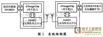
The designed wireless temperature sensor mainly consists of the following parts: temperature measurement, transmitting part, receiving part, LCD display part and control part. The system structure diagram is shown in Figure 1.
2.1 Temperature measurement circuit
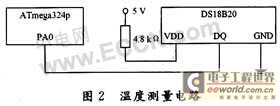
The temperature measurement circuit uses the 1-Wire bus digital temperature sensor DS18B20 produced by Dallas. The temperature measurement circuit is shown in Figure 2.
DS18B20 is a 3-pin TO-92 small package; the temperature measurement range is -55~125℃, it can be programmed to 9-12 bit A/D conversion accuracy, the temperature measurement resolution can reach 0.0625℃, and the measured temperature is serially output in a 16-bit digital format with sign extension.
The internal structure of DS18B20 mainly consists of 4 parts: 64-bit ROM, temperature sensor, non-volatile temperature alarm triggers TH and TL, and configuration registers. The 64-bit serial number in ROM is photoetched before leaving the factory. It can be regarded as the address sequence code of the DS18B20. The 64-bit serial number of each DS18B20 is different. The role of ROM is to make each DS18B20 different, so that multiple DS181E0s can be connected to one bus.
The temperature sensor in the DS18B20 measures the temperature in a 16-bit signed extended binary complement format, expressed as 0.062 5°C/LSB. For example, the digital output of +25.062 5°C is 0191H, and the digital output of -25.062 5°C is FF6FH.
The high and low temperature alarm triggers TH and TL, and the configuration register are composed of one byte of E2PROM. A memory function command can be used to write to TH, TL or the configuration register. The format of the configuration register is as follows:
R1 and R0 determine the number of digits of temperature conversion accuracy: R1R0 = "00", 9-bit accuracy, maximum conversion time is 93.75 ms; R1R0 = "01", 10-bit accuracy, maximum conversion time is 187.5 ms; R1R0 = "10", 11-bit accuracy, maximum conversion time is 375 ms; R1R0; "11", 12-bit accuracy, maximum conversion time is 750 ms; the default is 12-bit accuracy when not programmed. The design takes R1R0 = "11".
2.2 Wireless transceiver circuit
2.2.1 Interface between IA4421 and MCU
IA4421 supports SPI communication protocol. This design uses the high-performance microcontroller ATmega324p produced by ATMEL, USA, which has a built-in enhanced SPI interface and 32 kB FLASH, which can display Chinese characters on the LCD in the system. The interface circuit diagram of IA4421 and microcontroller is shown in Figure 3.
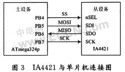
The enhanced serial peripheral interface SPI built into ATmega324p provides access to a full-duplex synchronous serial bus. The four signals used by SPI are MOSI, MISO, SCK, and SS. MOSI is used for serial data transmission from the master device to the slave device; MISO is used for serial data transmission from the slave device to the master device; SCK is used to synchronize serial data transmission between the master device and the slave device on the MOSI and MISO lines.
2.2.2 Wireless Transmission Timing
The transmission mode of IA4421 is the transmission register buffer data transmission mode, which is enabled by the 7th bit el of the configuration setting command. As can be seen from Figure 1, IA4421 has two 8-bit data registers. The transmitted data is first latched into one of the data registers. When the 5th bit et of the power management command is set to 1, the transmitter starts to send data out from the first register at the set bit rate.
Each time data is sent, 0xAA must be used as the leading code of the data, otherwise the external receiving device cannot receive the data. If the synchronous mode is used, 0x2DD4 must be used as the synchronous mode flag code before the data transmission can begin. Pin nIRQ can be used to detect whether the register is ready to receive the next byte from the microprocessor to send. If pin nIRQ becomes low, it means that the register is ready.
2.2.3 Wireless Reception Timing
There are two receiving modes for IA4421: one is to receive all the time; the other is FIFO mode. The former mode is not recommended and will cause a high bit error rate. This design adopts the latter mode. After the corresponding control words are set, the data has entered the buffer. If the pin nIRQ becomes low, it means that IA4421 is ready to receive data. At this time, the FIFO read command word is sent to start receiving.
2.3 Peripheral Antenna Design
IA4421 supports direct antenna drive, the design is quite simple and convenient, and the communication distance is long. A 50 Ω external spiral antenna and the corresponding differential circuit can realize data transmission and reception. The antenna designed in this system is realized by a 1.17 cm single-core copper wire with a diameter of 0.6 mm. The metal rod of a screwdriver is wound 7 times to form a spiral. After experiments, the actual effective communication distance can reach about 200 m, which meets the system requirements.
3 System Software Design
3.1 MCU Software Design
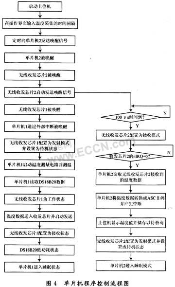
The microcontroller software mainly includes the main program, interrupt subroutine, temperature measurement subroutine, LCD conversion display, buzzer alarm subroutine, key subroutine and SPI subroutine. In order to reduce power consumption, interrupts are used to wake up the microcontroller for temperature measurement and other tasks. Therefore, the main program is relatively simple and is mainly responsible for the initialization of various parts of the system and the call of interrupts. After the system initialization is completed, it directly enters the sleep mode. When an interrupt arrives, the microcontroller exits the sleep mode and calls the interrupt subroutine to realize functions such as temperature measurement, conversion display, and temperature data transmission. The microcontroller control program flow chart is shown in Figure 4.
3.2 IA4421 Application Programming Design
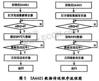
This system is based on the wireless transceiver chip IA4421 and the enhanced serial peripheral interface SPI of the single-chip microcomputer ATmega324p to realize wireless data transmission, and write its own upper layer application on the core protocol stack. The program flow chart of sending and receiving data is shown in Figure 5.
3.3 Low Power Design
As a wireless sensor, low power consumption can maximize the effective use time of the device. This system is battery-powered, so power consumption is definitely an issue that must be considered. In order to obtain the best performance, power loss and availability must be weighed according to the situation during design. In addition to selecting low-power devices, the power management program is also designed from the following aspects to minimize the power consumption of the wireless temperature sensor:
(1) Since the wireless temperature sensor is responsible for transmitting data to the control terminal, the control terminal of the upper computer can decide when to collect data and when to transmit data. It is very suitable to use the sleep mode and breathing mode to achieve the purpose of power saving by reducing the activity of IA4421 in the micro-network. The control terminal is used as the master device, and the power management program is designed in the application control layer of the terminal. The control terminal completes the query, pairing, and link establishment of the device. When the wireless sensor and the control terminal are successfully paired and connected, they enter the sleep mode. At this time, the master and slave devices still maintain the channel, but cannot send and receive data. When data transmission is required, exit the sleep mode and enter the breathing mode. Data is sent through the breathing time slot. The breathing interval can be set to 20 to 40 ms. If the interval is too large, it will cause obvious delay. After the data transmission is completed, it enters the sleep mode again, thereby reducing energy consumption as much as possible.
(2) Use the sleep mode of the microcontroller to achieve energy saving. When the IA4421 exits the standby state and sends instructions for data collection, the interrupt request flag nIRQ of the IA4421 generates a low level, and the change of the level on the interrupt flag generates an external interrupt to wake up the microcontroller and put it into working state.
4 Conclusion
The designed digital wireless temperature sensor can be applied to various occasions that require non-contact temperature measurement, and realize the "foreknowledge" of the on-site temperature. The design makes full use of the low power consumption characteristics of each chip to effectively extend the battery life. The wireless data transmission method is convenient and flexible to use. The system can be expanded into a network system to form a temperature collection network to meet the various needs of on-site control and measurement and control systems. This will be the subject of the author's next research and development.
Previous article:Research on automatic water level control system based on ultrasonic sensor
Next article:Research on tracking strategy of double-row sensors
- Popular Resources
- Popular amplifiers
- Molex leverages SAP solutions to drive smart supply chain collaboration
- Pickering Launches New Future-Proof PXIe Single-Slot Controller for High-Performance Test and Measurement Applications
- CGD and Qorvo to jointly revolutionize motor control solutions
- Advanced gameplay, Harting takes your PCB board connection to a new level!
- Nidec Intelligent Motion is the first to launch an electric clutch ECU for two-wheeled vehicles
- Bosch and Tsinghua University renew cooperation agreement on artificial intelligence research to jointly promote the development of artificial intelligence in the industrial field
- GigaDevice unveils new MCU products, deeply unlocking industrial application scenarios with diversified products and solutions
- Advantech: Investing in Edge AI Innovation to Drive an Intelligent Future
- CGD and QORVO will revolutionize motor control solutions
- Innolux's intelligent steer-by-wire solution makes cars smarter and safer
- 8051 MCU - Parity Check
- How to efficiently balance the sensitivity of tactile sensing interfaces
- What should I do if the servo motor shakes? What causes the servo motor to shake quickly?
- 【Brushless Motor】Analysis of three-phase BLDC motor and sharing of two popular development boards
- Midea Industrial Technology's subsidiaries Clou Electronics and Hekang New Energy jointly appeared at the Munich Battery Energy Storage Exhibition and Solar Energy Exhibition
- Guoxin Sichen | Application of ferroelectric memory PB85RS2MC in power battery management, with a capacity of 2M
- Analysis of common faults of frequency converter
- In a head-on competition with Qualcomm, what kind of cockpit products has Intel come up with?
- Dalian Rongke's all-vanadium liquid flow battery energy storage equipment industrialization project has entered the sprint stage before production
- Allegro MicroSystems Introduces Advanced Magnetic and Inductive Position Sensing Solutions at Electronica 2024
- Car key in the left hand, liveness detection radar in the right hand, UWB is imperative for cars!
- After a decade of rapid development, domestic CIS has entered the market
- Aegis Dagger Battery + Thor EM-i Super Hybrid, Geely New Energy has thrown out two "king bombs"
- A brief discussion on functional safety - fault, error, and failure
- In the smart car 2.0 cycle, these core industry chains are facing major opportunities!
- The United States and Japan are developing new batteries. CATL faces challenges? How should China's new energy battery industry respond?
- Murata launches high-precision 6-axis inertial sensor for automobiles
- Ford patents pre-charge alarm to help save costs and respond to emergencies
- New real-time microcontroller system from Texas Instruments enables smarter processing in automotive and industrial applications
- How to use an op amp to compare two states with different amplitudes
- [TI recommended course] #Live replay: 3 hours of practice + analysis: TI engineers take you step by step to fully get started with MSP430#
- Evaluation summary: Anxinke UWB indoor positioning module NodeMCU-BU01
- There is another big news recently. My god, a well-known electronic company in Shanghai is going to have a cut.
- stm32f030R8 Chinese reference material
- Recruitment: Executive Vice President of Automotive Electronics (Executive Vice President of New Energy)
- ATmega4809 Curiosity Nano Review + Unboxing and Powering on
- Sell an unused Jiuxintaike oscilloscope and get a Guwei desktop multimeter for free
- MSP430F1232 external 4M crystal oscillator cannot start
- Appreciation of TR components of early warning aircraft radar

 OP420GR


 京公网安备 11010802033920号