MODBUS is the most popular industrial protocol in use today for a variety of reasons . It is simple, cheap, versatile and easy to use.
Another advantage of MODBUS is that it can communicate over virtually any transmission medium, including twisted pair, wireless, optical fiber, Ethernet, telephone modems, mobile phones, and microwaves. This means that MODBUS connections can be easily established in a new or existing plant. In fact, a growing area of MODBUS applications is to provide MODBUS digital communications in older plants using existing twisted pair connections.
In this white paper we will examine how MODBUS works and look at some clever ways to use MODBUS in new and existing factories.
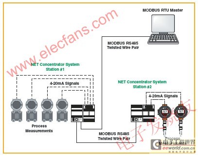
Figure 1: A MODBUS RTU network consisting of a "master station (a PLC or DCS)" and up to 247 "slave station" devices. Its network architecture is a multi-drop network connection.
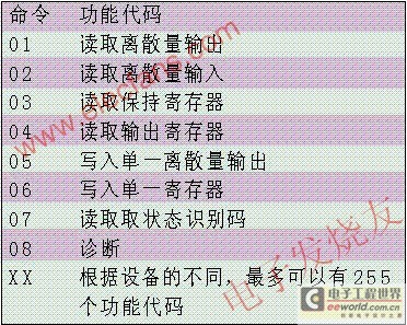
Table 1: Function codes
What is MODBUS?
MODBUS is a communication protocol developed by Modicon (now Schneider Electric) in 1979. Its purpose is to use a single twisted pair to communicate with many devices. The original solution used the RS232 interface, but MODBUS is also suitable for
RS485 interface in order to obtain higher communication rate, longer communication distance and realize true multi-branch network structure. MODBUS soon became a de facto standard in the field of automation industry, and Modicon also released it to the public without charging any royalties.
Today, the largest MODBUS user and supplier organization, MODBUS_IDA (www.MODBUS.org), continues to provide support for the MODBUS protocol worldwide.
MODBUS is a "master-slave" structure system, where the "master device" communicates with one or more "slave devices". Typical master devices are PLC (Programmable Logic Controller), PC, DCS (Distributed Control System) or RTU (Remote Terminal Unit). MODBUS-RTU slave devices are generally field instrument devices, all of which are connected to the system in a multi-branch network, see Figure 1. When a MODBUS-RTU master device wants to get data from a slave device, the master device sends a message containing the device address, the required data and a sum check code for error detection. All other devices on the network can see this message, but only the device with the specified address will respond.
Slave devices on a MODBUS network cannot initiate communications, they can only respond. In other words, they can only speak when someone speaks to them. Some manufacturers are developing "hybrid" MODBUS devices, which usually operate in a similar mode to MODBUS slave devices, but have the ability to "write", so sometimes these devices will operate as "pseudo-master devices".
The three most common MODBUS versions in use today are:
■ MODBUS ASC II
■ MODBUS RTU
■ MODBUS/TCP
All MODBUS messages are transmitted in the same format. The only difference between the three different types of MODBUS versions is how the message is encoded.
In the MODBUS RTU protocol, data is encoded in binary, and only one byte of data is required for communication. MODBUS RTU is an ideal communication protocol for RS232 networks with communication speeds between 1200 and 115K baud or RS485 networks with multi-branch networks. The most common communication rates for MODBUS RTU are 9600 and 19200 baud. MODBUS RTU is the most widely used industrial protocol, so the main part of this white paper will focus on the basic concepts and applications of MODBUS RTU.
MODBUS RTU Basics
To communicate with a slave device, the master device will send a message containing the following:
■ Device address
■ Function code
■ Data
MODBUS is the most popular industrial protocol in use today for a variety of reasons . It is simple, cheap, versatile and easy to use.
Another advantage of MODBUS is that it can communicate over virtually any transmission medium, including twisted pair, wireless, optical fiber, Ethernet, telephone modems, mobile phones, and microwaves. This means that MODBUS connections can be easily established in a new or existing plant. In fact, a growing area of MODBUS applications is to provide MODBUS digital communications in older plants using existing twisted pair connections.
In this white paper we will examine how MODBUS works and look at some clever ways to use MODBUS in new and existing factories.

Figure 1: A MODBUS RTU network consisting of a "master station (a PLC or DCS)" and up to 247 "slave station" devices. Its network architecture is a multi-drop network connection.

Table 1: Function codes
What is MODBUS?
MODBUS is a communication protocol developed by Modicon (now Schneider Electric) in 1979. Its purpose is to use a single twisted pair to communicate with many devices. The original solution used the RS232 interface, but MODBUS is also suitable for
RS485 interface in order to obtain higher communication rate, longer communication distance and realize true multi-branch network structure. MODBUS soon became a de facto standard in the field of automation industry, and Modicon also released it to the public without charging any royalties.
Today, the largest MODBUS user and supplier organization, MODBUS_IDA (www.MODBUS.org), continues to provide support for the MODBUS protocol worldwide.
MODBUS is a "master-slave" structure system, where the "master device" communicates with one or more "slave devices". Typical master devices are PLC (Programmable Logic Controller), PC, DCS (Distributed Control System) or RTU (Remote Terminal Unit). MODBUS-RTU slave devices are generally field instrument devices, all of which are connected to the system in a multi-branch network, see Figure 1. When a MODBUS-RTU master device wants to get data from a slave device, the master device sends a message containing the device address, the required data and a sum check code for error detection. All other devices on the network can see this message, but only the device with the specified address will respond.
Slave devices on a MODBUS network cannot initiate communications, they can only respond. In other words, they can only speak when someone speaks to them. Some manufacturers are developing "hybrid" MODBUS devices, which usually operate in a similar mode to MODBUS slave devices, but have the ability to "write", so sometimes these devices will operate as "pseudo-master devices".
The three most common MODBUS versions in use today are:
■ MODBUS ASC II
■ MODBUS RTU
■ MODBUS/TCP
All MODBUS messages are transmitted in the same format. The only difference between the three different types of MODBUS versions is how the message is encoded.
In the MODBUS RTU protocol, data is encoded in binary, and only one byte of data is required for communication. MODBUS RTU is an ideal communication protocol for RS232 networks with communication speeds between 1200 and 115K baud or RS485 networks with multi-branch networks. The most common communication rates for MODBUS RTU are 9600 and 19200 baud. MODBUS RTU is the most widely used industrial protocol, so the main part of this white paper will focus on the basic concepts and applications of MODBUS RTU.
MODBUS RTU Basics
To communicate with a slave device, the master device will send a message containing the following:
■ Device address
■ Function code
■ Data
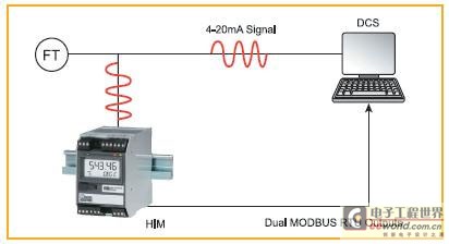
Figure 3: Peer-to-peer connection mode. In some cases, the control system cannot handle MODBUS signals. In this case, a peer-to-peer solution using dual NCS devices can be used to replace all direct control room cables with only one MODBUS cable. The analog outputs from the second NCS are then hardwired directly to the control system's I/O board.
Connecting MODBUS Devices
The easiest way to connect field devices to a process control system, PLC or industrial computer system is to simply connect digital and analog I/O to a distributed I/O system with MODBUS communication capabilities. For example, the NCS (Net Concentrator System) system from Moore Industries allows users to remotely connect analog and digital signals, and then connect to a MODBUS master device via twisted pair cables. Multiple NCS systems can be installed in several different locations throughout the plant, all connected via MODBUS (see Figure 2).
This solution is suitable for both new and existing plants. In many existing plants, field instrumentation is usually connected to the DCS or PLC system using multi-core cables, and each device transmits analog signals through a separate twisted pair cable. With the NCS system, only one of these cables is needed to transmit the MODBUS signal. This solution is particularly useful if the plant wants to add additional field instrumentation but does not want to install more cables (cable installation costs are usually $100 per foot). A distributed I/O system can meet the needs of all existing instrument I/O, or just use it to transmit data from all new field instrumentation.
In some cases, the control system cannot handle MODBUS signals. For example, the existing control system may be customized to handle 4-20 mA analog I/O and direct-wired digital I/O, and it is difficult to reprogram the existing old system to support MODBUS. Generally, users are generally not inclined to connect the newly added remote signals to the system by laying new cables or purchasing expensive MODBUS interface cards, because reprogramming MODBUS interface cards is very expensive. In this case, a peer-to-peer network solution can solve the problem well. For example, the CCS (Cable Concentrator System) and NCS (Net Concentrator System) systems from Moore Industries both have peer-to-peer communication capabilities.
NCS and CCS systems are very similar to a set of distributed I/O modules, but have greater built-in intelligence. NCS and CCS systems can be set up in either peer-to-peer or peer-to-host mode.
Using a peer-to-peer NCS system (see Figure 3), two network concentrators are configured; one is installed on site and the other is installed in the control room. The field instruments are connected to the remote NCS. The remote NCS is connected to the NCS in the control room via a twisted pair. The output of the control room NCS is then hardwired to the analog I/O disk of the existing control system. With this method, the analog signal from the newly added field transmitter can be connected to the control system through the existing analog I/O card of the factory in the state of the original analog signal. This greatly reduces the programming and debugging work caused by the new signal compared to the new digital interface card. This peer-to-peer network solution can also meet the requirements of two-way communication, in which case both the field side and the control room side of the system can have input and output capabilities.
HART over MODBUS
Another challenge facing older plants is finding an inexpensive and convenient way to take advantage of the installed and "to-be-installed" HART smart instruments. HART stands for Highway Addressable Remote Transducer. HART is a digital protocol designed to enable transmitters to be transmitted over the twisted-pair copper wiring of traditional plant installations.
The HART transmitter transmits digital data while controlling the analog signal. This allows users to configure, test and diagnose the transmitter remotely or locally through the connection at any point on the twisted pair. HART slave devices can be connected in a point-to-point manner or in a multi-drop network. Point-to-point connection is the most common HART connection method, in which the HART transmitter represents the required process variable by changing the current on the analog loop. Of course, it is also possible to monitor only the digital HART data; however, few people do this in point-to-point operation. While the HART transmitter controls the current, it can also send a variety of digital information packets through the HART data stream. Both process variable data and digital information data can be transmitted by HART slave devices or transmitters. This data can be used to monitor the health of the instrument or used by the process control system or asset management system to optimize the process, help achieve tighter control or prevent unexpected process fluctuations. In some cases, existing plants may have hundreds of HART-capable instruments. Unfortunately, for a variety of reasons, many plants never develop the potential capabilities of these HART instruments.
In the current environment where asset management systems, remote diagnostic systems and advanced control are widely used, many factories want to extract the digital information of HART instruments, but their control systems and existing wiring methods cannot support this requirement. These control systems may not be able to extract HART data from the digital signal, or these control systems only want to see hard-wired digital and analog I/O signals. A HART instrument can send up to four process variables via HART signals: PV (primary variable), SV (secondary variable), TV (third variable), FV (fourth variable). In addition, various bits and bytes of status data can also be transmitted by HART signals. However, if the control system cannot read these additional process variable data or any other diagnostic information and status information from the digitized HART signal, then this data is wasted.
Users can certainly choose to take advantage of this HART data, even with older systems in existing plants. Some DCS companies offer new, upgraded analog I/O cards that are capable of "understanding" this HART data. However, such cards are usually three to five times more expensive than traditional analog I/O cards. There are also HART signal mixing units that can be installed in existing analog I/O loops. These interface units have RS422 and RS485 output ports and can be connected to asset management systems or DCSes. Of course, the price of these HART signal mixing units is also prohibitive. Another option is to use a HART to MODBUS converter, such as the HIM (HART Signal Interface Module) from Moore Industries, which is a cost-effective and flexible solution that can selectively monitor only a few loops or many loops at a reasonable price.
Using a HART interface module that supports MODBUS RTU communication, all HART data can be collected into the control system simply and inexpensively (see Figure 4). This HIM is an intelligent device that can operate as a HART master station at the front end and as a MODBUS RTU slave device at the back end. The HIM can extract all HART data from the analog signal of the transmitter without affecting or interfering with the 4 to 20 mA signal connected to the control system. The HIM can also provide an LCD display window, three 4 to 20 mA signals, two relay outputs and an optional dual MODBUS RTU output. When the user uses the MODBUS option, the HART data is digitally mapped in the MODBUS memory map of the HIM, and then the PLC or DCS as the MODBUS RTU master can obtain the required data from this memory map. Connecting multiple HIMs in a multi-drop network and transmitting HART data through the RS485 interface is essentially a small-scale asset management system, but at a fraction of the cost.
Wireless MODBUS
A MODBUS network can be set up fairly easily to work over a wireless connection (see Figure 5). Essentially, any wireless connection does little more than replace the twisted pair cables with transmitters/receivers at each end of the network. Many manufacturers of radios support the MODBUS protocol. However, because radios and modems use some encryption and time delay schemes, it is important to check with the vendor of your wireless device before assuming it supports the MODBUS protocol.
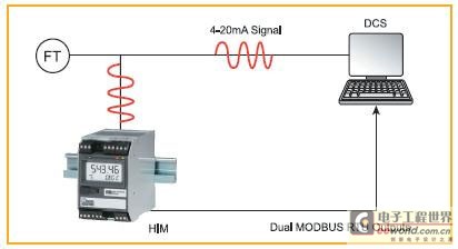
Figure 4: A HART interface module (HIM) extracts the digitized data from the HART signal and stores it in its own MODBUS memory map so that any MODBUS master device can read the data. The original 4-20mA signal is still connected to the control system as before.
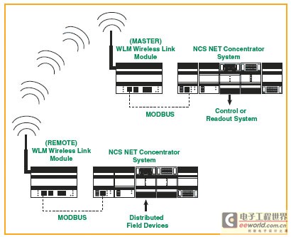
Figure 5: A wireless interface (such as the Wireless Link Module from Moore Industries) uses an RF link instead of twisted-pair wiring.
Obviously, the main advantage of wireless MODBUS is to save the cost of laying lines. In the past, it was very expensive to monitor and control signals from tank farms, wellheads and various remote locations.
Fortunately, wireless MODBUS transmission is transparent to the control system or master and slave stations. For example, the old systems in the existing factories mentioned above, such host systems do not even know that there is a wireless MODBUS network, because they
There is no need to confront this wireless MODBUS network at all. When a MODBUS master station makes a request to a slave station, the message packet is sent to the radio transmitter. Usually the radio transmitter will requeue and encrypt the message packet before transmitting. Once the RF (radio frequency) message packets are received by the slave station, the slave station will decrypt them and sort them to represent a valid MODBUS message packet again. If the message packet is not damaged or garbled, it will be sent to the requested slave station. The slave station will respond to the request of the master station and the process will be repeated again.
Sometimes it is important to pay special attention to a MODBUS communication parameter called "timeout". Timeout indicates how long the MODBUS master will wait for a slave to respond before trying to resend the message. Depending on the quality of the radio, the transmission of the message packet may be delayed, which may cause unnecessary retries and retransmissions. With today's FHSS (Frequency Hopping Spread Spectrum) radios, most of these parameters can be modified to efficiently transmit MODBUS message packets. Many communication problems can usually be avoided by proper analysis of the site selection, including signal strength analysis and band noise analysis.
MODBUS over Ethernet
MODBUS/TCP is often understood as MODBUS on Ethernet. In fact, in general, MODBUS/TCP is just a simple compression of MODBUS message packets using the TCP/IP standard. This allows MODBUS/TCP devices to easily connect and communicate through existing Ethernet and fiber optic networks. Compared with the RS485 interface, MODBUS/TCP also allows the use of many more addresses, can adopt a multi-master architecture, and the transmission rate can reach GB level. Although MODBUS RTU has a limit of no more than 247 nodes per network, the number of slaves in the MODBUS/TCP network is only limited by the capacity of the network physical layer. Usually the number of slaves is about 1024. The rapid popularity of Ethernet in the process control and automation industry has made MODBUS/TCP the most widely used and fastest growing industrial protocol supported by Ethernet.
Although all PLC vendors have their own Ethernet protocols, almost all of them support MODBUS/TCP. Even for those PLC vendors that do not currently support MODBUS/TCP, they can find many companies such as Prosoft Technologies and SST that can provide MODBUS/TCP communication cards for bottom-mounted PLC products and accessories such as independently installed gateways.
Another advantage of MODBUS/TCP is its multi-master capability. Unlike MODBUS RTU and MODBUS ASCII, MODBUS/TCP allows multiple masters to obtain data from the same slave at the same time. Why does MODBUS/TCP have this capability? This is because by using Ethernet over TCP/IP, multiple messages can be sent, buffered, and delivered without token passing or taking full control of the bus. This is a common situation for many RS485 and RS422 protocols.
Bring control to the field via MODBUS
So far, we have only covered simple MODBUS data acquisition systems. Another solution is also possible, that is, to install the control equipment on site and then communicate with the central control system via MODBUS. The network concentrator NCS mentioned above also has a powerful CPU (central processing unit) and real-time control kernel. It can also be programmed to perform control functions such as PID control, ON/OFF control, field alarms, complex arithmetic operations, diagnosis, and alarm monitoring.
Because it has PLC-like logic, PID-type control functions, and advanced computing capabilities, an NCS can usually meet the functional requirements of a PLC, industrial computer, or a small DCS, and its price is only a fraction of the latter. Although the MODBUS protocol does not have the capabilities of other protocols such as Foundation Fieldbus and CIP (Common Industrial Protocol), it does meet the needs of many applications. In these applications, users like to control on-site and monitor and control the site through Ethernet. The MODBUS protocol is the most cost-effective and convenient solution to meet this need.
Another "intelligent" MODBUS device with control capabilities is the MDS Equation Station from Moore Industries. This is a multi-function controller that can perform many types of control functions and calculations. With the MDS Equation Station, a PLC or large controller is no longer required to implement simple control tasks, multivariable control tasks (such as monitoring and controlling the pulp level in a digester or using input signals from multiple flow, temperature and pressure transmitters to perform mass flow calculations). Up to 127 MDS modules can be installed on a MODBUS network to control the plant or collect signals from the entire plant.
PID (proportional, integral and differential) controllers were originally stand-alone, non-communication controllers. As PLCs and DCSs have become intelligent, so too have PID controllers. Today, many end users still favor single-loop controllers that are simple to read and program. Digital communication protocols such as MODBUS can breathe some new life into these instruments that have always been stand-alone. By connecting these controllers to a multi-branch network, you can create your own small distributed control system, see Figure 6.
MODBUS: Universal Interface
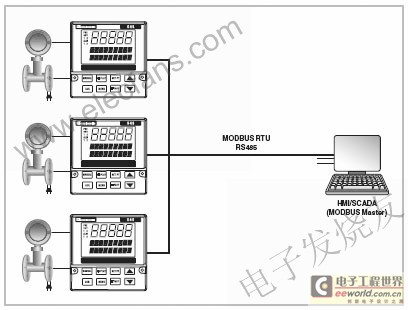
Figure 6: Devices with MODBUS functionality (such as 1/4 DIN 545 dual-loop PID controllers) can place control functions in the field. Connecting these MODBUS devices into a multi-drop network and sending their outputs to a Windows-based SCADA system creates a small distributed control system.
While the modern control field continues to generate and apply advanced concepts such as fieldbus and mesh networks, MODBUS's simplicity and its ease of implementation on many communication media have always made it the most widely supported and widely used industrial protocol in the world. When users of existing old control systems find themselves needing to expand field instruments or add remote controllers, they will use MODBUS as a simple solution to complex problems. When users try to connect an external device to the control system, using the device's MODBUS interface always proves to be the easiest way. Although MODBUS is one of the oldest communication methods, it is also the most popular communication method for many reasons. MODBUS is easy to use, very reliable, low-cost and can be connected to almost all sensors and control devices in the control industry.
Previous article:Research on Network Control Technology Based on CNC Machine Tools
Next article:AAS Engine Assembly Line Control Solution
- Popular Resources
- Popular amplifiers
- Molex leverages SAP solutions to drive smart supply chain collaboration
- Pickering Launches New Future-Proof PXIe Single-Slot Controller for High-Performance Test and Measurement Applications
- CGD and Qorvo to jointly revolutionize motor control solutions
- Advanced gameplay, Harting takes your PCB board connection to a new level!
- Nidec Intelligent Motion is the first to launch an electric clutch ECU for two-wheeled vehicles
- Bosch and Tsinghua University renew cooperation agreement on artificial intelligence research to jointly promote the development of artificial intelligence in the industrial field
- GigaDevice unveils new MCU products, deeply unlocking industrial application scenarios with diversified products and solutions
- Advantech: Investing in Edge AI Innovation to Drive an Intelligent Future
- CGD and QORVO will revolutionize motor control solutions
- Innolux's intelligent steer-by-wire solution makes cars smarter and safer
- 8051 MCU - Parity Check
- How to efficiently balance the sensitivity of tactile sensing interfaces
- What should I do if the servo motor shakes? What causes the servo motor to shake quickly?
- 【Brushless Motor】Analysis of three-phase BLDC motor and sharing of two popular development boards
- Midea Industrial Technology's subsidiaries Clou Electronics and Hekang New Energy jointly appeared at the Munich Battery Energy Storage Exhibition and Solar Energy Exhibition
- Guoxin Sichen | Application of ferroelectric memory PB85RS2MC in power battery management, with a capacity of 2M
- Analysis of common faults of frequency converter
- In a head-on competition with Qualcomm, what kind of cockpit products has Intel come up with?
- Dalian Rongke's all-vanadium liquid flow battery energy storage equipment industrialization project has entered the sprint stage before production
- New breakthrough! Ultra-fast memory accelerates Intel Xeon 6-core processors
- New breakthrough! Ultra-fast memory accelerates Intel Xeon 6-core processors
- Consolidating vRAN sites onto a single server helps operators reduce total cost of ownership
- Consolidating vRAN sites onto a single server helps operators reduce total cost of ownership
- Allegro MicroSystems Introduces Advanced Magnetic and Inductive Position Sensing Solutions at Electronica 2024
- Car key in the left hand, liveness detection radar in the right hand, UWB is imperative for cars!
- After a decade of rapid development, domestic CIS has entered the market
- Aegis Dagger Battery + Thor EM-i Super Hybrid, Geely New Energy has thrown out two "king bombs"
- A brief discussion on functional safety - fault, error, and failure
- In the smart car 2.0 cycle, these core industry chains are facing major opportunities!
- msp430 MCU ADC12 sampling voltage to 1602 display program
- Based in Chengdu, we are looking for embedded software engineers with experience in HiSilicon, Ingenic, and MStar chip IPC
- "Lost events"? See how to tune the Tracealyzer streaming mode
- USB instruments will become the mainstream of measuring instruments
- This article will help you understand the advantages and disadvantages of various switching power supply topologies
- A small program that converts Matlab results into C language
- LTC2325-16 + ZYNQ data acquisition PL end functions are all completed
- [Goodbye 2021, Hello 2022] You summarize, I give gifts!
- Please advise on the external magnetic field distribution of a C-shaped energized coil
- How to deduce normalized parameters from transfer functions and then design filters

 OPA827AD


 京公网安备 11010802033920号