This paper applies the timer function of WDM in redundancy technology , provides a solution for system fault detection and switching technology, and takes the dual redundant CAN bus interface board as an example to test the feasibility of this design.
1 Redundancy Technology
There are two types of redundancy technology: working redundancy and backup redundancy. Working redundancy is to repeatedly configure key equipment on a dual or triple basis. These devices are in working operation at the same time. If a device fails during operation, it will automatically leave the system, but it will not affect the normal operation of the system. The backup redundancy method is to put one device into operation, and the other redundant device is in hot standby state, but not put into operation. Once the online operating device fails, the backup device is immediately put into operation. Commonly used redundant systems can be divided into three types according to their structure: parallel system, backup system and voting system. The simplest redundant design is a parallel device. Other methods include series-parallel or series-parallel hybrid devices and majority voting devices. When the reliability requirements of a certain part are very high, but the current technical level and methods are difficult to meet, redundant technology may become the only better design method. However, redundant design often increases the volume, weight, cost and complexity of the system accordingly. Therefore, except for important key equipment, redundant technology is not suitable for general products.
Although redundant configuration increases system investment, it improves the mean time between failures (MTBF) of the entire user system and shortens the mean time to repair (MTR). Therefore, in the control system of important occasions, the use of redundant technology can effectively improve the reliability of the system.
For a redundant system to work, it is usually completed by the cooperation of hardware and software. In terms of hardware, there need to be several identical devices that can work independently. In terms of software, it means that while realizing the system functions, there must be error detection functions and dynamic switching functions, and the switching action must be completed in the shortest possible time. The following takes the dual CAN bus interface card as an example to mainly describe the implementation details of this backup redundancy design from the software aspect.
2 Hardware Design
The CAN controller uses Philips' SJA1000, which works in BasicCAN mode or PeliCAN mode. The PeliCAN mode supports CAN 2.0B protocol and uses an 8-bit address/data multiplexed bus interface.
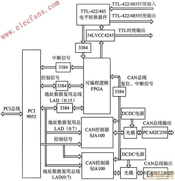
As shown in Figure 1, the PCI bus dual CAN interface card provides two independent CAN interfaces with two SJA1000 chips. The 8-bit address/data bus, read/write control signal, and latch signal of each chip are directly connected to PCI9052. The output signal of SJA1000 is transmitted to the CAN transceiver PCA82C250 through an optical coupler. The power supply of PCA82C250 is an isolated power supply provided by an isolated power conversion module. The reset signal of the CAN bus is provided by the FPGA, and the interrupt signal of the CAN controller SJA1000 is output to the FPGA.

Figure 1 CAN redundancy module system structure diagram.
3 Software Design
3.1 WDM mode driver
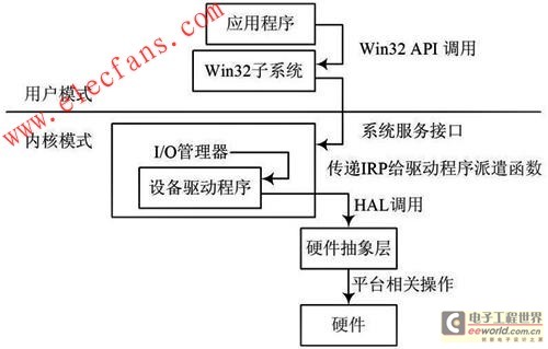
In Windows XP operating system, applications running in user mode access hardware resources by calling kernel mode drivers through Win32 API. This kernel mode driver is WDM (Windows Driver Model) driver, which is a new driver model proposed by Microsoft in Windows XP operating system, supporting plug-and-play, power management and I/O management functions. Figure 2 is the system structure of Windows XP.
As shown in Figure 2, the device driver is a component of the operating system and is managed and mobilized by the I/O Manager.
Each time the I/O manager receives a request from a user application, it creates an I/O request packet (IRP) data structure and passes it to the driver as a parameter. The driver identifies the physical device object (PDO) in the IRP to distinguish which device it is sent to. The IRP structure stores information such as the type of request, the first address of the user buffer, and the length of the user request data. After the driver processes the request, it fills in the structure with information about the processing result, calls IoCompleteRequest to return it to the I/O manager, and the user application's request is returned immediately. When accessing hardware, the driver implements it by calling the function of the hardware abstraction layer.

Figure 2 Windows XP system structure.
WDM can be developed using DDK, DriverWorks and other development tools. The following focuses on the use of timing query in this WDM driver example to achieve CAN bus redundancy.
3.2 Drive redundancy design
In this design, the CAN path uses two-way redundancy, so that when one CAN bus interface fails, it can be easily switched to another CAN bus interface.
Fault detection is implemented in the timer. There are two types of timer objects in DriverWorks, namely the 1 Hz timer attached to the device object and the timer defined by the KTimedCallback class. The WDM timing method is implemented through them. KTimedCallback is a derived class of KTimer. KTimer encapsulates the system timer and constitutes a distribution object timer class, which can be used for synchronization purposes. The KTimedCallback class contains the system delayed procedure call (DPC) object. When the timer times out, the system calls the DPC. The member functions of KTimedCallback are mainly Set and SetPeriodic. Set is used to set the parameters of a valid timer, and SetPeriodic sets the parameters of a periodic timer. Set and SetPeriodic start the timer and establish an association with the callback function when setting the timing parameters. The callback function is called after the timer times out.
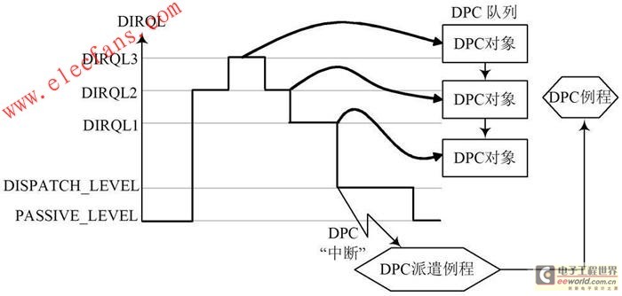
The specific switching work is done in the DPC. DPC is a deferred procedure call. Some operations are not suitable for processing in the ISR and need to be placed in the DPC with fewer restrictions, such as notification event flags, etc. DPC is a general mechanism, but it is usually used in interrupt processing. In the most common case, the ISR determines the completion of the current request and requests a DPC. After that, the kernel calls this DPC routine at the DISPATCH_LEVEL level.
Therefore, code in a DPC has fewer restrictions than code in an ISR.
In particular, DPC routines can call routines such as IoCompleteRequest or Io StartNextPacket, which are logically necessary at the end of an I/O operation. Figure 3 describes the specific DPC call processing process.

Figure 3 DPC processing process.
The redundant switching query time can be modified by adding a switching time period item in the device properties, and can be modified online by modifying the device properties. After the modification, the device manager automatically updates the driver.
In the dual CAN redundant system, the software design is relatively more complicated than the hardware structure. The key lies in the CAN system fault detection and the automatic switching of the CAN system. Due to the use of two completely independent transmission media, bus drivers and bus controllers, they can detect the faults of their own channels independently, such as CANH and CANL short circuit, CANH or CANL disconnection, CANH and ground short circuit, CANL and power short circuit, bus driver damage, etc. In actual debugging, it is found that if CANH and CANL are disconnected or there is only one transmitter on the bus, the send/receive error counter will continue to increase to 128, making the node in the ignore error state; while CANH and CANL short circuit, CANH and ground short circuit or CAN L and power short circuit will cause the send/receive error counter to continue to increase to 256, making the node in the bus off state. Therefore, by calling the CAN redundant module in the node state change interrupt subroutine, the purpose of realizing the above-mentioned automatic fault detection and automatic switching of the CAN system can be achieved.
3.3 Redundancy test
During the test, a two-channel CAN analyzer is used to connect the A and B channels of this CAN board respectively. During the process of continuously sending data from channel A to the analyzer, the link is manually disconnected, and the standby channel B starts to work, and the switch is successful. The test of the redundant switching time can be judged by comparing the difference in the amount of data between the sender and the receiver. The specific method is to continuously send data packets at the sender with a cycle of 10 ms. Under normal circumstances, the number of data packets at the sender is equal to the number of data packets at the receiver. During the switching action, some data packets will be discarded. At this time, the difference between the data packets at the sender and the receiver is calculated and multiplied by 10 ms, which is the switching time of this switch. In this example, through multiple such tests, the average switching time is about 30 ms, which can fully meet the requirements for high reliability of computer systems.
4 Conclusion
A system design method for device redundancy is proposed, which provides a solution for system fault detection and switching technology. Using this method, a dual-redundant CAN bus board and WDM driver under Windows XP system are designed. The module works stably, data transmission is reliable, and redundant switching is feasible. The timing query time can be modified online according to actual use requirements. This redundancy implementation method has certain practical value in improving equipment reliability.
Previous article:Design of LD automatic temperature control system based on MAX1968
Next article:Buck topology application based on LM5642
- Popular Resources
- Popular amplifiers
- Molex leverages SAP solutions to drive smart supply chain collaboration
- Pickering Launches New Future-Proof PXIe Single-Slot Controller for High-Performance Test and Measurement Applications
- CGD and Qorvo to jointly revolutionize motor control solutions
- Advanced gameplay, Harting takes your PCB board connection to a new level!
- Nidec Intelligent Motion is the first to launch an electric clutch ECU for two-wheeled vehicles
- Bosch and Tsinghua University renew cooperation agreement on artificial intelligence research to jointly promote the development of artificial intelligence in the industrial field
- GigaDevice unveils new MCU products, deeply unlocking industrial application scenarios with diversified products and solutions
- Advantech: Investing in Edge AI Innovation to Drive an Intelligent Future
- CGD and QORVO will revolutionize motor control solutions
- Innolux's intelligent steer-by-wire solution makes cars smarter and safer
- 8051 MCU - Parity Check
- How to efficiently balance the sensitivity of tactile sensing interfaces
- What should I do if the servo motor shakes? What causes the servo motor to shake quickly?
- 【Brushless Motor】Analysis of three-phase BLDC motor and sharing of two popular development boards
- Midea Industrial Technology's subsidiaries Clou Electronics and Hekang New Energy jointly appeared at the Munich Battery Energy Storage Exhibition and Solar Energy Exhibition
- Guoxin Sichen | Application of ferroelectric memory PB85RS2MC in power battery management, with a capacity of 2M
- Analysis of common faults of frequency converter
- In a head-on competition with Qualcomm, what kind of cockpit products has Intel come up with?
- Dalian Rongke's all-vanadium liquid flow battery energy storage equipment industrialization project has entered the sprint stage before production
- Allegro MicroSystems Introduces Advanced Magnetic and Inductive Position Sensing Solutions at Electronica 2024
- Car key in the left hand, liveness detection radar in the right hand, UWB is imperative for cars!
- After a decade of rapid development, domestic CIS has entered the market
- Aegis Dagger Battery + Thor EM-i Super Hybrid, Geely New Energy has thrown out two "king bombs"
- A brief discussion on functional safety - fault, error, and failure
- In the smart car 2.0 cycle, these core industry chains are facing major opportunities!
- The United States and Japan are developing new batteries. CATL faces challenges? How should China's new energy battery industry respond?
- Murata launches high-precision 6-axis inertial sensor for automobiles
- Ford patents pre-charge alarm to help save costs and respond to emergencies
- New real-time microcontroller system from Texas Instruments enables smarter processing in automotive and industrial applications
- ARM immediate number explanation--the difference between LDR and MOV
- i.MX283 latest virtual machine system guide
- TI C5000 compiler error message list
- TI Award-winning Live Broadcast: Talking about "packaged antenna" smart millimeter wave sensors, even novices can handle industrial robots
- The voltage of the TPS73033 buck chip drops to 0.7V after the load is connected
- Wi-Fi 6 is here to provide network coverage for the entire home. Will you adopt it?
- Common APDU instruction error codes for CPU cards
- [GigaDevice GD32F310 Review] +ADC Data Collection
- [Mill Edge AI Computing Box FZ5 Review] Development Board Target Classification Demo
- [Domestic RISC-V Linux Board Fang·Starlight VisionFive Trial Report] GPIO Development Basics: From Principle to Practice

 LM1896N-2/B+


 京公网安备 11010802033920号