0 Introduction
The original microcomputer control system of the JHML-T1000 wet laminating machine made in Taiwan in a printing factory adopts a distributed control structure of various boards (signal acquisition input card, various control output cards, tension control board, display card, etc.) and buses. Due to the long history and the influence of the production environment and the lack of effective tension control in the production process, the system is unstable. This leads to a decline in product quality and output. Tension control is the core of the whole machine and the main factor affecting product quality. In the laminating process, if the tension is properly controlled, there will be no longitudinal or transverse wrinkles, and the material itself will not undergo plastic deformation. In the printing process, as long as the tension is stable, the registration accuracy and scrap rate of the printing are easy to control. The higher the machine speed, the more important the tension control becomes. To obtain high-quality products, it is necessary to equip it with a tension control system with complete functions. Therefore, a comprehensive technical transformation of the tension control system of the laminating machine was carried out: the original microcomputer control system was replaced with a control system with PLC as the core, in order to perform stable and reliable tension control on the equipment, thereby meeting the needs of the production process.
1 System Introduction
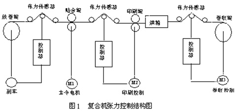
The structure of the tension control system of the laminating machine is shown in Figure 1. The whole system is divided into two parts: unwinding, tension passive control and laminating, printing and winding active control.

1.1 Unwinding tension driven control
The unwinding tension control is divided into two sections, namely the tension control between the paper material and the composite roller and the tension control between the aluminum foil material and the composite roller. Passive constant tension unwinding is adopted during unwinding. Therefore, as the roll diameter decreases during unwinding, the tension must remain basically constant. The magnetic powder brake must adjust the transmission torque to meet the requirement of constant tension. At the same time, because the distance between the two sections is relatively short, the initial tension value should be set smaller. It is worth noting that the heavier the roll, the greater the unwinding tension; when the roll diameter is the same, the wider the roll, the greater the tension.
1.2 Lamination-Printing-Rewinding Tension Control
The laminating-printing-winding tension is caused by the speed difference between the laminating roller, printing roller and winding roller. In the laminating machine, the tension of this part is adjusted by adjusting the speed output of the laminating roller motor, printing roller motor and winding roller motor. In addition to being affected by the speed difference, it is also related to factors such as the actual substrate expansion rate, thickness change, drying temperature, high drying zone length, and the transmission speed of the material belt. If the expansion rate of the substrate is greater, it is easier to deform under the action of tension, so the rectification output should be appropriately adjusted for substrates of different materials to change the speed difference, so as to obtain a suitable tension value. If the thickness of the substrate is uneven, the pressure of the laminating roller and the printing roller will fluctuate, resulting in changes in speed and affecting the tension. If the tension of this part is too small, wrinkles will appear, and even pile-up will occur. But it cannot be too large. Too much tension will cause the material belt to deform and even longitudinal wrinkles to appear.
2 System Solution
In view of the defects of the original discrete board structure of the industrial computer system, a tension control system with PLC as the core is adopted. The digital input and output are realized by the input and output of CPU226 and the 8-way input of the digital expansion module EM221 and the 16-way input/16-way output of EM223; the analog input uses the EM235 module, and the analog output uses the EM235 module and EM232 module. The overall structure diagram of the system is shown in Figure 2. Two magnetic powder brakes are used to control the tension of the unwinding process, 4-way tension detectors realize the detection input of each section of tension, and 3 DC speed regulators realize the control of 3 drag DC motors. Finally, the logical control of the system is completed through PLC.
3 System Hardware
In the design of the tension control system, Siemens S7-200 series small PLC is used as the logic control core to control each link in the production process of the composite machine. Constant tension control of the production process is achieved by controlling the magnetic powder brake and DC traction motor. According to the sequence of the composite process, the entire tension control system can also be divided into the following four parts according to different process processes.
3.1 Unwinding control
1. Unwinding process structure
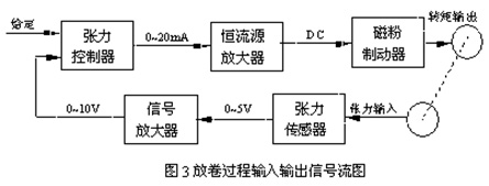
The tension control of the unwinding process is divided into two sections: the tension control between the paper material and the composite roller, and the tension control between the aluminum foil material and the composite roller. The unwinding adopts passive constant tension unwinding. Therefore, as the roll diameter decreases during the unwinding process, the tension must remain basically constant. The magnetic powder brake must adjust the braking torque to meet the constant tension. The tension sensor detects the load tension and sends it to the controller after passing through the tension signal amplifier. The controller integrates the given and feedback tension, outputs the control signal, and drives the magnetic powder brake to act on the reel through the power amplifier to form a tension closed-loop control system.
2. Input and output signals
The input and output signal flow of the unwinding process is shown in Figure 3. The tension sensor installed at both ends of the tension sensing roller converts the induced pressure into a voltage signal, which is amplified into a 0-10V standard signal and input into the PLC analog input port. In the tension control process, after comparing the given value with the feedback value, a tension deviation e (t) is obtained. After being processed by the PID algorithm subroutine, the control quantity u (t) is obtained. After being amplified, the magnetic powder brake is driven to control the brake current size, and then the brake output brake torque is controlled, so that the unwinding tension is maintained within a certain range and the tension is constant.

3.2 Fit control
After unwinding, the paper and aluminum foil pass through the guide rollers in the form of material strips under the action of traction. Before the laminating operation, coating must be performed first. Coating is to apply a chemical substance similar to glue on the material strip so that laminating can be performed. After coating, the paper and aluminum foil enter the laminating roller under the action of traction. Under the dual action of the pressure of the laminating roller and the laminating wheel and the coating glue, the paper and aluminum foil are tightly adhered together to complete the laminating process. The laminating process is open-loop for PLC. However, the DC speed regulator and the DC motor are controlled by a logic non-circulating current dual closed-loop of speed and current, which ensures the accuracy and stability of the motor speed control, so for the DC speed regulator-DC motor system, it is still closed-loop control. PLC only provides a speed given value.
3.3 Printing Control
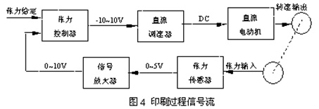
The composited material belt enters the printing unit through the guide roller. After a series of printing processes, it comes out of the printing unit under the traction force applied by the traction roller and enters the next process. In this process, the tension signal collected by the sensor is first processed by the signal transmitter and then enters the feedback input of the tension controller. After comparing with the tension set value, the control signal is output to control the operation of the DC speed regulator. The DC speed regulator controls the speed of the DC motor according to the output of the tension controller to complete the closed-loop control of the tension in the printing process. The controller inputs have tension feedback input and set input, and the controller output is speed control output. The input and output signal flow chart 4 is shown.

3.4 Motor drive circuit for lamination, printing and winding process
The motor drive of this system adopts SIEMENS's SIMOREGK 6RA24 full-digital DC speed control device as the drive and control device of the DC drive motor. The speed control system has 4 analog input ports, 5 analog output ports, 8 switch input ports and 4 switch output ports. Its device software is easy to replace and is very convenient to use.
Since the compound machine only has short-term forward and reverse rotation, and the rest are forward rotation, its short-term forward and reverse rotation (jog) can be solved by the contactor. Therefore, a single-phase speed limiter is selected. The control function of the digital speed regulator is realized by software, so parameter setting is required. This system has no special requirements for control accuracy and does not use a speed measurement interface.
4 System Software
The main program flow chart of the control system is shown in Figure 5.

The main program is first initialized. The PLC starts the first scan, runs the startup initialization subroutine, and completes the initialization of the system memory data by calling the program. Then comes the power supply and fault detection input part. If the power is off, the program runs directly to the end and the program execution is completed; if the power is on, the program starts to detect the fault input. If there is no fault, continue the following scan; if a fault is found, call the alarm subroutine, then the program turns to the end and the program execution is completed. Then comes the automatic/manual selection. Manual operation is only used for debugging equipment, while automatic operation is used for production. If it is manual, call the manual operation subroutine. Next is the run and stop judgment. When the input is stop, the program executes the stop subroutine; when the input is run, the program executes the run process. Next is the speed change operation. If the system setting changes, run the speed change subroutine to make the system keep approaching and finally reach the new system speed. Finally, there is the tension PID adjustment part. This part completes the system tension control by controlling two magnetic powder brakes and two DC motors.
5 Conclusion
This system uses SIEMENS S7-200 small PLC as the control core, realizes the input of field signals and real-time control of the system, and ensures the stability and rapidity of the response. The software design adopts modular design ideas, and the program structure is clear, which brings convenience to future maintenance and improvement. The tension control system is the core of the whole machine operation and the main factor affecting product quality. The operation results show that the tension control system of the composite machine operates normally and has good performance.
Previous article:PLC-based rooftop air conditioner with fresh air heat pump
Next article:Applying PLC automatic control principles in configuration software control systems
- Molex leverages SAP solutions to drive smart supply chain collaboration
- Pickering Launches New Future-Proof PXIe Single-Slot Controller for High-Performance Test and Measurement Applications
- CGD and Qorvo to jointly revolutionize motor control solutions
- Advanced gameplay, Harting takes your PCB board connection to a new level!
- Nidec Intelligent Motion is the first to launch an electric clutch ECU for two-wheeled vehicles
- Bosch and Tsinghua University renew cooperation agreement on artificial intelligence research to jointly promote the development of artificial intelligence in the industrial field
- GigaDevice unveils new MCU products, deeply unlocking industrial application scenarios with diversified products and solutions
- Advantech: Investing in Edge AI Innovation to Drive an Intelligent Future
- CGD and QORVO will revolutionize motor control solutions
- Innolux's intelligent steer-by-wire solution makes cars smarter and safer
- 8051 MCU - Parity Check
- How to efficiently balance the sensitivity of tactile sensing interfaces
- What should I do if the servo motor shakes? What causes the servo motor to shake quickly?
- 【Brushless Motor】Analysis of three-phase BLDC motor and sharing of two popular development boards
- Midea Industrial Technology's subsidiaries Clou Electronics and Hekang New Energy jointly appeared at the Munich Battery Energy Storage Exhibition and Solar Energy Exhibition
- Guoxin Sichen | Application of ferroelectric memory PB85RS2MC in power battery management, with a capacity of 2M
- Analysis of common faults of frequency converter
- In a head-on competition with Qualcomm, what kind of cockpit products has Intel come up with?
- Dalian Rongke's all-vanadium liquid flow battery energy storage equipment industrialization project has entered the sprint stage before production
- Allegro MicroSystems Introduces Advanced Magnetic and Inductive Position Sensing Solutions at Electronica 2024
- Car key in the left hand, liveness detection radar in the right hand, UWB is imperative for cars!
- After a decade of rapid development, domestic CIS has entered the market
- Aegis Dagger Battery + Thor EM-i Super Hybrid, Geely New Energy has thrown out two "king bombs"
- A brief discussion on functional safety - fault, error, and failure
- In the smart car 2.0 cycle, these core industry chains are facing major opportunities!
- The United States and Japan are developing new batteries. CATL faces challenges? How should China's new energy battery industry respond?
- Murata launches high-precision 6-axis inertial sensor for automobiles
- Ford patents pre-charge alarm to help save costs and respond to emergencies
- New real-time microcontroller system from Texas Instruments enables smarter processing in automotive and industrial applications
- When connecting the STEVAL-IDB008V2 board to BlueNRG GUI, the device cannot be found.
- Happy holidays to everyone. During the holidays, goldfish eat meat and stay at home. Here are the statistics
- Discussion: 5G is coming, what skills do we need to acquire? (Give away Chip Coins)
- A LiDAR Level Meter Silo Level Measurement Solution
- Multisim simulation IR2103
- 7 common 51 single-chip microcomputer clock circuit diagrams, collect them!
- [Ebit E840-DTU Review] Performance Introduction
- Design of DCDC voltage stabilization power supply and peripheral circuit for voltage stabilization chip selection
- [Repost] Enter the top ten most commonly used electronic components, how many do you know? (I)
- Help, which chip can be found in TINA TI simulation software to make APFC switching power supply?

 MAXM17502 Data Sheet


 京公网安备 11010802033920号