The condition monitoring and fault diagnosis of industrial equipment effectively ensure the smooth operation of the equipment and play an increasingly important role in the predictive maintenance of equipment. In order to meet the needs of petrochemical enterprises for condition monitoring and fault diagnosis, a portable comprehensive equipment condition monitoring and diagnostic instrument is designed. The OMAPL138 dual-core processor launched by TI has powerful complex data processing capabilities and reliable real-time performance. It can realize high-performance dual-channel data acquisition and signal analysis, and display FFT spectrum diagrams, axis trajectory and other functions on site.
The OMAPL138 processor combines the advantages of DSP and ARM processors in real-time performance and calculation accuracy. DSP performs signal processing tasks, and ARM can run embedded operating systems and graphical interfaces to complete waveform display, storage and control of peripheral devices. Data communication between DSP and ARM is realized by DSP/BIOS bridge.
1 Hardware Design
1.1 Processor and Peripheral Circuit Design
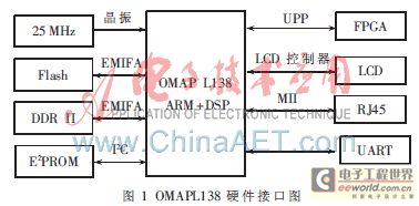
The OMAPL138 chip uses the C6748 core and ARM926EJ-S core, and the main frequency of the two processors supports up to 456 MHz. C6748 is a fixed-point floating-point digital signal processor core. It has significantly lower power consumption than TMS320C6000 devices and can achieve code compatibility. ARM926EJ-S is a 32-bit reduced instruction set processor core that can execute 32-bit and 16-bit instruction sets and process 32-bit, 16-bit, and 8-bit data. The ARM core has a coprocessor CP15, as well as 8 KB of RAM and 64 KB of ROM. The interface supports 1 10/100 M Ethernet interface, DDR2 memory controller, 1 EMIFA interface, 2 sets of I2C and SPI interfaces, and 2 sets of McBSP interfaces [1]. The hardware connection diagram of OMAPL138 is shown in Figure 1.

OMAPL138 uses EMIFA interface to control the operation of Flash and uses GPCM 16 bit operation mode. FLASH uses a 32 MB chip from SPANSION to store BOOT content and application programs. In addition, the data address line sequence of OMPAL138 uses SMALL_EIDEN mode. When connecting the address line and the data line, it should be noted that the sequence of the most significant bit and the least significant bit is inconsistent with the processors of PowerPC and other series.
OMAPL138 supports two formats, mDDR and DDR2. This design uses DDR2 SDRAM as the memory of the chip. DDR2 SDRAM is implemented by a DDR2 chip MT47H64M16HR. The capacity of a single chip is 128 MB, the bit width is 16 bits, and it is divided into 8 BANKs internally. Only the 4 registers SDCR, SDRCR, SDTIMR1, and SDTIMR2 need to be configured to realize the configuration of DDR2. The maximum speed of the DDR2 controller of OMAPL138 supports 150 MHz.
OMAPL138 is connected to an E2PROM through the I2C interface. The model is AT24C32CN, which has 4 096×8 bit storage space for storing sensor calibration parameters and version information.
In addition, OMAPL138 is connected to the PC through the MII interface. It can also be easily debugged with the host computer through the UART interface to print debugging information.
1.2 Data acquisition circuit design
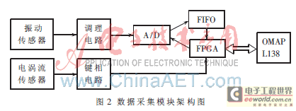
The system data acquisition part consists of two high-speed ADs, a large-capacity buffer FIFO and FPGA. FPGA is responsible for high-speed data acquisition logic control and cache FIFO logic control [2]. The collected signal is transmitted to the DSP core in OMAP, and then the signal is processed and the algorithm is completed. Finally, it is sent to the ARM core for waveform display and other functions. The data acquisition module architecture is shown in Figure 2.
2 Software Design
The software design of the equipment status monitoring and diagnostic instrument includes: design of the boot program, cutting and transplanting of the operating system kernel, customizing the file system, and developing the application program and interface. In OMAP, the DSP core runs the DSP/BIOS real-time system, and the ARM core runs the Windows CE system. DSP/Link provides a dual-core communication architecture for the processor. On the DSP side, DSP/Link exists as a driver of DSP/BIOS. On the ARM side, DSP/Link exists as a peripheral and accesses this device through the function library of the application layer for operation.
2.1 Operating system construction and transplantation
The board support package (BSP) is a layer between the motherboard hardware and the operating system. Its main purpose is to support the operating system so that it can run better on the hardware motherboard. A typical Windows CE board support package includes four components: the boot loader Boot loader, the OEM adaptation layer (OAL), the device driver, and the system image configuration file. The application integrated development environment Platform Build can generate specific operating system images for different hardware based on specific BSPs. The embedded operating system Windows CE is tailored and compiled with the board support package to generate an operating system that can run on the hardware, so as to achieve the purpose of porting Windows CE to the hardware system. By modifying some of the Windows CE codes, the expansion of new software features required by the system is realized.
The design and development of device drivers, including drivers for data acquisition system, infrared temperature measurement module, panel function keyboard module and power management module, etc.; and a friendly and flexible interface is provided for the system and application to facilitate upper-level calls.
2.2 Design of data acquisition function module
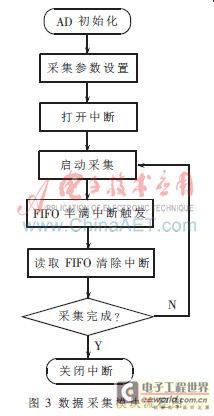
The data acquisition module is the core part of the equipment status monitoring and diagnostic instrument. The efficiency and stability of its driver are key factors affecting the entire system. Its basic workflow is shown in Figure 3.

Before starting data acquisition, you can set the number of sampling points, sampling frequency, and single/dual channel acquisition. During the acquisition process, when the A/D converter completes a cycle of conversion, it will send an interrupt to the FPGA, and the FPGA will send a write signal to the FIFO and write the converted data into the FIFO. When the FIFO is half full, its half-full flag will send an interrupt signal. After receiving the signal, the FPGA controls OMAP to perform a read operation on the FIFO. The difference between the non-triggered acquisition mode and the triggered acquisition mode is that in the non-triggered acquisition mode, the start and stop signals of the A/D are provided by OMAP. When conversion is required, OMAP sends a start conversion signal to start the AD conversion and stop it; in the triggered acquisition mode, the acquisition start and stop signals are provided by the key phase signal.
The portable device status monitoring and diagnostic instrument with OMAPL138 as the processor platform meets the requirements of low power consumption and high performance of handheld instruments. The collaborative work of ARM core and DSP core not only meets the requirements of high-speed digital signal processing and completes complex fault diagnosis algorithms, but also has powerful peripheral management and control capabilities. At the same time, Window CE also provides users with a rich and friendly operation interface to meet user needs.
References
[1] Texas Instrument. OMAP-L138 Technical Reference Manual [EB/OL]. 2009.
[2] Ren Lei, Lin Yan, Zhang Ganmoyang.
Design of data communication between
OMAP-L137
and
ADS1178
based on CPLD
[J]. Microcontrollers and Embedded Systems Applications, 2009, 8: 26-28.
[3] Wu Yu. Research and development of embedded data acquisition system [D]. Beijing: Beijing University of Chemical Technology, 2008.

The vibration signal collected by the piezoelectric acceleration sensor first passes through the signal conditioning and amplification circuit, and then passes through the second-order Butterworth bandpass filter, and a pure acceleration signal can be collected by AD. The acceleration signal passes through the first-level integration circuit to obtain the speed signal, and then passes through the first-level integration circuit to obtain the displacement signal.
In the detection and diagnosis of rotating machinery, the key phase signal occupies an important position. The key phase signal generated by the eddy current sensor is generally a negative pulse of about -10 V. After DC isolation, inversion, and hysteresis comparison, it becomes a narrow pulse of 3.3 V and is sent to the FPGA as a trigger signal for triggering acquisition.
The FPGA uses the Cyclone series of Altera, which is connected through the UPP (Universal Parallel Port) interface on the OMAP to transmit the high-speed data signal to the DSP core of the OMAP. The FPGA accepts the trigger of the key phase circuit as the phase zero point of data acquisition, and controls one or two ADs to collect the conditioned vibration signal at the same time. The collected values are first cached in the FIFO and then transmitted to the OMAP through the FPGA.
In the DSP core of OMAP, the collected vibration waveform can be processed by digital signal to complete Fourier transform, axis trajectory, dynamic balancing and other algorithms. Finally, the processing results are transmitted to the ARM core through the DSP/BIOS bridge, and the time domain diagram, spectrum diagram and axis trajectory diagram are displayed in the application.
Previous article:Advantech Launches SusiAccess - Smart Solution for Remote Monitoring of Embedded Devices
Next article:Design and implementation of submission and review system
- Popular Resources
- Popular amplifiers
- Molex leverages SAP solutions to drive smart supply chain collaboration
- Pickering Launches New Future-Proof PXIe Single-Slot Controller for High-Performance Test and Measurement Applications
- CGD and Qorvo to jointly revolutionize motor control solutions
- Advanced gameplay, Harting takes your PCB board connection to a new level!
- Nidec Intelligent Motion is the first to launch an electric clutch ECU for two-wheeled vehicles
- Bosch and Tsinghua University renew cooperation agreement on artificial intelligence research to jointly promote the development of artificial intelligence in the industrial field
- GigaDevice unveils new MCU products, deeply unlocking industrial application scenarios with diversified products and solutions
- Advantech: Investing in Edge AI Innovation to Drive an Intelligent Future
- CGD and QORVO will revolutionize motor control solutions
- Innolux's intelligent steer-by-wire solution makes cars smarter and safer
- 8051 MCU - Parity Check
- How to efficiently balance the sensitivity of tactile sensing interfaces
- What should I do if the servo motor shakes? What causes the servo motor to shake quickly?
- 【Brushless Motor】Analysis of three-phase BLDC motor and sharing of two popular development boards
- Midea Industrial Technology's subsidiaries Clou Electronics and Hekang New Energy jointly appeared at the Munich Battery Energy Storage Exhibition and Solar Energy Exhibition
- Guoxin Sichen | Application of ferroelectric memory PB85RS2MC in power battery management, with a capacity of 2M
- Analysis of common faults of frequency converter
- In a head-on competition with Qualcomm, what kind of cockpit products has Intel come up with?
- Dalian Rongke's all-vanadium liquid flow battery energy storage equipment industrialization project has entered the sprint stage before production
- Allegro MicroSystems Introduces Advanced Magnetic and Inductive Position Sensing Solutions at Electronica 2024
- Car key in the left hand, liveness detection radar in the right hand, UWB is imperative for cars!
- After a decade of rapid development, domestic CIS has entered the market
- Aegis Dagger Battery + Thor EM-i Super Hybrid, Geely New Energy has thrown out two "king bombs"
- A brief discussion on functional safety - fault, error, and failure
- In the smart car 2.0 cycle, these core industry chains are facing major opportunities!
- The United States and Japan are developing new batteries. CATL faces challenges? How should China's new energy battery industry respond?
- Murata launches high-precision 6-axis inertial sensor for automobiles
- Ford patents pre-charge alarm to help save costs and respond to emergencies
- New real-time microcontroller system from Texas Instruments enables smarter processing in automotive and industrial applications
- Smart Camera Structure Design--Update on Recent Amateur DIY
- First experience - unboxing
- TMC5130 is used as a driver to drive the motor. Why does the motor hum when it is stationary?
- Live broadcast at 10 am today [TI's optimized solutions in industrial multi-protocol communication applications]
- Made an LED music spectrum analyzer
- EEWORLD University Hall----TI Smart Speaker and Sound Bar- New Power Design Trend
- What parameters should be paid attention to when selecting optocouplers?
- Is there any difference between bit rate and airspeed?
- TFT LCD display realizes dial pointer clock
- Power conversion module 220V to 18V

 NJM14558V


 京公网安备 11010802033920号