For a long time, due to the harsh operating environment, imperfect monitoring and maintenance methods, fans have been constantly experiencing faults such as broken reducer teeth, burned bearings, bent transmission shafts, damaged coupling diaphragms, and even broken blades. The fan monitor based on MAXl320 is a very important part of this monitoring and diagnostic system, and its key component is the analog/digital conversion chip. MAXl320 is a parallel 14-bit 8-channel synchronous acquisition A/D conversion chip launched by Maxim, which is very suitable for data acquisition of fan speed, acceleration, displacement, process quantity, etc. Here we introduce a data acquisition interface solution based on ARM7 fan monitor, the A/D chip uses MAXl320, and the processor of the monitor uses Philips' LPC2290.
l MAXl320 Overview
The MAX1320 is an 8-input channel, 14-bit high-speed analog-to-digital converter with independent sample/hold (T/H) circuits that provide simultaneous sampling for each channel. The device has a first-in/first-out (FIFO) function that reduces interface overhead and allows conversion results to be read at the end of a conversion or between conversions.
1.1 Pins and their characteristics
The pins and their characteristics are as follows:
CH0~CH7: 8-channel analog input port.
D0~D13: 14-bit parallel digital output, of which DO~D7 are bidirectional data lines.
CS, RD, WR: chip select signal, read signal, and write signal respectively.
CONVST: Conversion start signal. When CONVST is low, it tracks and acquires the analog signal, and starts the conversion when it rises.
EOC, EOLC: End of conversion output (EOC), low level indicates the end of conversion of a channel, and the conversion result of this channel can be read. Last end of conversion output (EOLC), low level indicates the end of conversion of the last channel, and then the conversion results of all enabled channels can be read continuously.
CLK, INTCLK/EXTCLK: External clock input pin (CLK), clock mode selection input (INTCLK/EXTCLK). This pin is connected to AVDD to select the internal clock (clock frequency is 10 MHz) and to AGND to select the external clock input (100 kHz~12.5 MHz).
ALLON: Channel enable input. If this pin is connected to a high level, all input channels (CH0 to CH7) will be enabled. If it is connected to a low level, only the selected channel will perform A/D conversion.
SHDN: Power-down input pin. SHDN=0 selects normal mode, SHDN=1 selects power-down mode.
1.2 MAXl320 working process
MAXl320 has a total of 8 analog input channels, which can be selected and used through register settings. When ALLON is set to a low level, set the register to select the channel to be opened, pull down CS and WR at the same time, and then write data to data lines D0~D7. D0~D7 correspond to channels CH0~CH7 in turn. The corresponding channel is selected by writing "1" to data lines D0~D7. If ALLON is set to a high level, all channels are turned on and there is no need to set the configuration register. When the analog input channel is determined, send a low level to CONVST, which starts an analog/digital conversion. Assuming that all 8 analog channels are used, the 8 sample/hold devices inside the chip track the input signal before the rising edge of CONVST arrives. On its rising edge, the input analog signal is sampled/held, and then the analog/digital conversion is performed. Once EOC has a falling edge, it indicates that one conversion is completed. Once EOLC has a falling edge, it indicates that all analog/digital conversions are completed. There are two ways to read the conversion results: you can read the converted data after each conversion and then proceed to the next conversion (see Figure 1(a)); or you can wait until all channels are converted and read them one by one. During the entire reading process, the EOLC signal remains low until the next falling edge of CONVST (see Figure 1(b)).

2 Application of MAXl320 in Data Acquisition of Fan Monitor
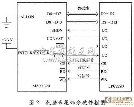
The fan monitor is based on the ARM7 processor, which uses the LPC2290 from Philips. The hardware block diagram of its data acquisition part is shown in Figure 2.

The actual fan monitor can selectively measure multiple signal inputs at the same time according to different requirements in different time periods, so the pin AL-LON is grounded here, and the configuration register is written according to the requirements to open the channels that need to be opened, and the unused channels are closed to reduce power consumption. Considering that the environment used by this monitor is relatively harsh, if an external clock is used, the input clock signal is easily interfered, which will cause the entire data acquisition module to be unstable, so the pin INTCLK/EXTCLK is also connected to +3.3 V, and the internal clock (10 MHz) is selected. The 10 MHz frequency can fully meet the sampling requirements of this monitor.
3 Design of MAxl320 peripheral analog circuit
3.1 Analog Input Circuit

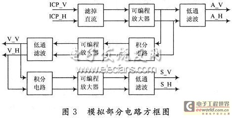
The most common measurement signal parameters monitored by industrial fan monitors are fan shaft vibration acceleration, velocity, and displacement. This monitor can be connected to acceleration sensors, velocity sensors, and displacement sensors. The specific analog circuit block diagram is shown in Figure 3. The ICP acceleration sensor connected in Figure 3 is only a set of ICP analog inputs. It is divided into two inputs of ICP_V (vertical direction) and ICP_H (horizontal direction). AV, A_H, V_V, V_H, S_V, and S_H are the vertical and horizontal outputs of acceleration, velocity, and displacement respectively. If a velocity sensor is used, the first stage outputs velocity, the second stage outputs displacement, and the third stage circuit is meaningless. If a displacement sensor is used, the first stage outputs displacement, and the second and third stage circuits are meaningless. The operational amplifiers used in the low-pass filter circuit and the integration circuit are all integrated chips MAX4164, which integrates 4 low-power operational amplifiers. The low-pass filter circuit uses a second-order low-pass filter. For the ordinary first-order low-pass filter circuit, an RC link is added to increase the attenuation slope to make the filtering effect better. The integration circuit is the most typical integration operation circuit. A 1μF capacitor is added to the input end to filter out the DC component. A resistor is connected in parallel to the integration capacitor to prevent saturation or cutoff caused by excessive gain of low-frequency signals and integration drift. The value is generally greater than or equal to 10 times the input resistance. The programmable amplifier uses LTC6911-2, which is a two-matched programmable amplifier integrated chip. By writing values to the 3-bit programmable interface G1, G2, G3, 0, 1, 2, 4, 8, 16, 32, 64 output magnifications can be obtained.
3.2 Multiplexer Circuit
The analog signal input of the fan monitor used in industrial sites is generally more than 8 channels, so a multi-channel selection circuit can be added to the 8-channel input of MAXl320. The monitor uses CD74HC4052 to form a multi-channel selection circuit. CD74HC4052 is a dual power input, four-group channel selection chip. By selecting S0 and S1, any of the four groups can be output, and the maximum analog input range is ±5 V.
4 Experimental debugging
4.1 Programming
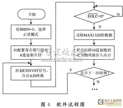
The bottom-level driver of MAXl320 is developed in the integrated development environment ADSI.2, and the A/D conversion software flow is shown in Figure 4.

In order to control the sampling frequency of ADC in practical applications, this design uses a timer to perform timing operations on the entire sampling and data reading process of A/D, so that the monitor can change the sampling frequency according to various requirements on site. Among them, the software design of A/D conversion has changed: when a relatively low sampling frequency (100 Hz~5 kHz) is used, the timing time is relatively long. Because the software design of this monitor is based on the μC/Os-Ⅱ embedded system, the timer interrupt method is used, which will avoid waiting for the timing to arrive in the sampling task and reduce the operating efficiency of the multi-task operating system. Put the entire process of sampling and reading data in the interrupt service program. When the timing time is up, it will immediately jump to the interrupt service program to perform the sampling and reading operation, and then jump out of the interrupt program to continue to execute the operations behind the main program; when a relatively high sampling frequency (5~40 kHz) is used, because the timing time is very short, the query method can be used to query the timer interrupt flag bit all the time. When the interrupt flag is set, the sampling and reading operation is performed.
4.2 Experimental Test
Use the internal clock and turn on all 8 channels. Input a 1 kHz sine wave (peak-to-peak value is 2 V) to channels 0 to 7. Connect D0 to D13 of MAXl320 and D0 to D13 of LPC2290. Connect the other corresponding pins according to Figure 3. Start A/D conversion. Because the data of the 8 channels are the same, only read the converted value of channel O. The results are shown in Table 1.

The above test result data is the sampling point value of sampling 1 kHz sine wave for 1 cycle. A total of 38 points are sampled, of which 19 are positive and 19 are negative. Table 1 lists only some representative values. By marking these sampling points on the coordinates, the input sine wave can be restored. Through the oscilloscope, it can be seen that the time used to track and capture the actual signal and the sampling signal is basically the same as the theoretical value. However, waiting for the EOLC signal to become low takes time to execute the program itself, and the reading of the conversion result is limited by the speed of the processor data bus itself, so the entire sampling frequency is lower than the ideal value. Some improvements can be made to reduce the impact of these two factors on the sampling frequency, namely:
(1) EOLC can be connected to the external interrupt signal pin of the processor and the interrupt method can be used, which has a faster response speed than the original query method;
(2) It can increase the CPU clock cycle or reduce the number of CPU cycles occupied by read and write operations.
5 Conclusion
From the above experimental test results and the sampling time (about 0.3μs) and conversion time (3.7μs) measured by the oscilloscope, it can be seen that when the eight channels work simultaneously, the total sampling and conversion time is about 4μs, so it can be calculated that the throughput of each channel is about 250kS/s, which can fully meet the data acquisition requirements of the on-site wind turbine monitor.
Previous article:Acceleration Method for MPEG Audio Layer III Compression Using DSP
Next article:Application of Embedded Ethernet in Power High Voltage Monitoring System
- Popular Resources
- Popular amplifiers
- Molex leverages SAP solutions to drive smart supply chain collaboration
- Pickering Launches New Future-Proof PXIe Single-Slot Controller for High-Performance Test and Measurement Applications
- CGD and Qorvo to jointly revolutionize motor control solutions
- Advanced gameplay, Harting takes your PCB board connection to a new level!
- Nidec Intelligent Motion is the first to launch an electric clutch ECU for two-wheeled vehicles
- Bosch and Tsinghua University renew cooperation agreement on artificial intelligence research to jointly promote the development of artificial intelligence in the industrial field
- GigaDevice unveils new MCU products, deeply unlocking industrial application scenarios with diversified products and solutions
- Advantech: Investing in Edge AI Innovation to Drive an Intelligent Future
- CGD and QORVO will revolutionize motor control solutions
- Innolux's intelligent steer-by-wire solution makes cars smarter and safer
- 8051 MCU - Parity Check
- How to efficiently balance the sensitivity of tactile sensing interfaces
- What should I do if the servo motor shakes? What causes the servo motor to shake quickly?
- 【Brushless Motor】Analysis of three-phase BLDC motor and sharing of two popular development boards
- Midea Industrial Technology's subsidiaries Clou Electronics and Hekang New Energy jointly appeared at the Munich Battery Energy Storage Exhibition and Solar Energy Exhibition
- Guoxin Sichen | Application of ferroelectric memory PB85RS2MC in power battery management, with a capacity of 2M
- Analysis of common faults of frequency converter
- In a head-on competition with Qualcomm, what kind of cockpit products has Intel come up with?
- Dalian Rongke's all-vanadium liquid flow battery energy storage equipment industrialization project has entered the sprint stage before production
- Allegro MicroSystems Introduces Advanced Magnetic and Inductive Position Sensing Solutions at Electronica 2024
- Car key in the left hand, liveness detection radar in the right hand, UWB is imperative for cars!
- After a decade of rapid development, domestic CIS has entered the market
- Aegis Dagger Battery + Thor EM-i Super Hybrid, Geely New Energy has thrown out two "king bombs"
- A brief discussion on functional safety - fault, error, and failure
- In the smart car 2.0 cycle, these core industry chains are facing major opportunities!
- The United States and Japan are developing new batteries. CATL faces challenges? How should China's new energy battery industry respond?
- Murata launches high-precision 6-axis inertial sensor for automobiles
- Ford patents pre-charge alarm to help save costs and respond to emergencies
- New real-time microcontroller system from Texas Instruments enables smarter processing in automotive and industrial applications
- Summary of performance indicators of integrated operational amplifiers
- EEWORLD University - Using the 75 W TAS6424-Q1 Class D Audio Amplifier for DC and AC Load Diagnostics
- EEWORLD University Hall----Live playback: High-performance i.MX RT processors help smart nodes achieve machine learning without Internet access
- Help, failed to create new IP core
- Setting the switching frequency of the switching power supply chip LTM4613
- Does the power layer of a four-layer board need to be made into a complete plane?
- [Register to enjoy gifts] element16 sincerely invites you to visit the 2019 Munich Shanghai Electronics Show
- EEWORLD University Hall----Live playback: AM57X platform features and typical applications
- 【ST NUCLEO-H743ZI Review】(1) First experience lighting up the LED
- bluenrg chat example

 EL2228CY-T13


 京公网安备 11010802033920号