Compared with general serial communication buses, CAN bus has the advantages of high reliability, high real-time performance, and strong flexibility in data communication. It is not only widely used in the automotive industry, but also expanded to many fields such as mechanical industry, robots, and CNC machine tools. Especially in the case of large-scale data communication processing, high reliability and real-time response, the single-channel CAN bus cannot meet the requirements of actual communication. Therefore, a design scheme based on a multi-channel real-time CAN simulator is introduced.
1 CAN bus technology introduction
1.1 CAN bus characteristics
CAN (Controller Area Network) bus is a serial multi-master controller area network bus. It has high network security, communication reliability and real-time performance, and is simple and practical with low network cost. It is mainly used as a network for various process monitoring and control. CAN was originally designed by BOSCH of Germany for automobile monitoring and control systems. Due to its excellent characteristics and extremely high reliability, CAN bus is particularly suitable for the interconnection of monitoring equipment in industrial processes.
1.2 CAN Communication Protocol
There are two different frame formats in the CAN 2.0B version protocol. The difference is the length of the identifier field. The frame with an 11-bit identifier is called a standard frame, and the frame with a 29-bit identifier is called an extended frame. The extended format is a new feature added to the CAN 2.0B protocol. When transmitting messages, different frames have different transmission structures. Only when the frame is transmitted strictly in accordance with the structure can it be correctly received and sent by the node. The following will introduce the structures of the four transmission frames:
(1) Data frame: Data frame transfers data from the transmitter to the receiver. The CAN protocol has two data frame types: standard 2.0A and standard 2.0B. The essential difference between the two is the length of the ID. In type 2.0A, the length of the ID is 11 bits; in type 2.0B, the length of the ID is 29 bits. It consists of 7 fields: frame start, arbitration field, control field, data field, CRC check code field, response field, and frame end.
(2) Remote frame: The bus unit sends a remote frame to request the transmission of a data frame with the same identifier. The node receiving data can request the source node to send data by sending a remote frame. It consists of 6 fields: frame start, arbitration field, control field, check field, response field, and frame end.
(3) Error frame: Any unit that detects a bus error will send an error frame. It consists of two fields: error flag and error boundary. When the receiving node finds that the message on the bus is wrong, it will automatically send an "active error flag". Other nodes will send an "error acknowledgment flag" after detecting the active error flag.
(4) Overload frame: Overload frame is used to provide additional delay between adjacent data frames or remote frames. It consists of an overload flag and an overload delimiter. An overload frame can only be started after a frame ends. When the receiver needs too much time to process the current data before receiving the next frame, or when a dominant level is detected in the interframe gap field, an overload frame is sent.
1.3 CAN protocol controller
At present, the mainstream CAN protocol controller generally uses I/O bus (SJA1000, etc.) or SPI interface (M2P2515, etc.) to communicate with the processor. This design uses SJA1000 controller.
SJA1000 is an independent CAN controller, which is used in the field of mobile target and industrial LAN control. SJA1000 has two working modes: BasicCAN and PeliCAN. This design adopts PeliCAN working mode. SJA1000 is used to complete all the functions of the physical layer and data link layer specified by the CAN protocol. It can support the timing characteristics of multiple processors, such as Intel mode or Motorola mode. The interface with the microprocessor is very simple. The microprocessor accesses SJA1000 in the same way as accessing external memory.
SJA1000 is connected to the CAN bus through the CAN controller interface, i.e., the PCA82C250 chip. The CAN transceiver uses the PCA82C250 of Philips, which is the interface between the CAN controller and the physical bus. It provides the differential launch and reception capabilities of the bus and is fully compatible with the ISO11898 standard. It has three different working modes, i.e., high speed, slope control, and standby, which can be selected according to actual conditions. The PCA82C250 is used in the hardware circuit to increase the communication distance, improve the instantaneous anti-interference ability of the system, protect the bus, reduce interference, etc.
2 System Design
2.1 System Design
According to the bus classification of general computers, a multi-channel real-time CAN bus simulator can be developed based on the ISA bus. According to the CAN bus communication principle, the following two design schemes can be proposed:
(1) ISA bus + CAN communication controller;
(2) ISA bus + microprocessor + CAN communication controller. The difference between these two designs lies in whether a processor is used to strengthen control.
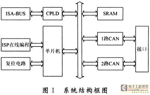
Since CAN bus communication requires high real-time performance, and the multi-channel design meets practical needs, a single-chip microcomputer is used to be responsible for the communication function of the CAN bus. Here we mainly introduce the design part between the single-chip microcomputer and the CAN controller, and its system design block diagram is shown in Figure 1.

The single-chip microcomputer uses DALLAS's DS89C430, which is the highest performance among the current 8051 compatible microcontrollers. It has a redesigned processor core, and at the same crystal frequency, the speed of executing instructions is 12 times that of the original 8051 microprocessor. Features: high-speed 8051 architecture, one clock per machine cycle; on-chip memory 16 KB/32 KB/64 KB flash memory, programmable in application, programmable in system through serial port; compatible with 8051 pins and instruction sets; four bidirectional, 8-bit I/O ports; three 16-bit timers/counters; 256 B temporary RAM, etc. Some of its functions can be selected according to the needs of actual applications. With the rapid development of programmable logic devices, its application field continues to expand, and it can be used for decoding and decoding. The use of CPLD can improve system integration, reduce noise, and enhance system reliability. Therefore, the latching and decoding between the single-chip microcomputer and the CAN controller uses Xilinx's XC95144CPLD chip, which optimizes system resources and reduces its power consumption.
2.2 System Hardware Design
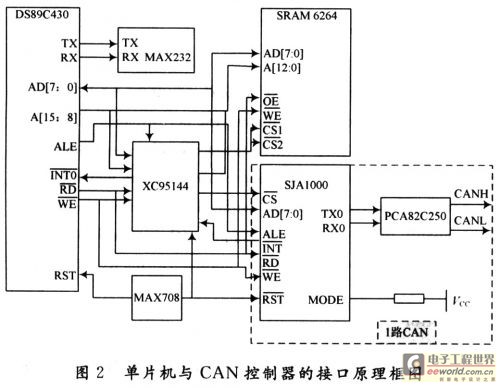
This part consists of a single-chip microcomputer, a CAN controller, a CAN transceiver, and an SRAM memory. The single-chip microcomputer is mainly used for system calculation and information processing functions; the CAN controller is mainly used for system communication; the CAN transceiver is mainly used to enhance the driving ability of the system; and the SRAM is mainly used to cache data. The sending process of the system is: after the single-chip microcomputer processes the information transmitted by the peripheral device, it writes it into the sending buffer of the CAN controller according to the format specified by the CAN specification, and starts the sending command to send the data to the CAN bus; the receiving process is: the CAN controller automatically receives data from the CAN bus, and stores it in the CAN receiving buffer after filtering, and sends an interrupt request to the single-chip microcomputer. At this time, the single-chip microcomputer can read the data to be received from the CAN receiving buffer. The microprocessor interface mode provided by SJA1000 is a typical INTEL or MOTOROLA address data multiplexing bus mode. The main signals are address data signals AD7~AD0, address selection signal ALE, chip select signal CS, read signal RD, write signal WR, and mode selection signal MODE. When MODE=1, it is INTEL mode; when MODE=0, it is MOTOROLA mode. The bus modes described below are all INTEL modes. When ALE is valid, AD7~AD0 pins transmit address signals, and when RD or WR is valid, data signals are transmitted. Here, they are connected to the PO port of the microcontroller, and the RD and WR signal lines are connected to the read/write signal lines of the microcontroller respectively. The specific scheme is shown in Figure 2. Due to space limitations, the connection diagram of 1-way CAN is given in the dotted line, and the connection method of 2-way CAN is the same.

The chip select signal of SRAM and CAN controller. Since the microcontroller can be accessed by query or interrupt, the interrupt method is used here to select CAN multi-channel access to meet the needs of data processing at different communication rates. The address line and data line of SRAM are separated, so the 74LS373 latch is used to realize the latch function. The XC95144CPLD chip and VHDL hardware description language can be used to realize the latch, decoding and other functions.
2.3 CPLD design part
2.3.1 Structural design
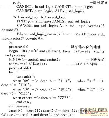
The input signal of CPLD is the signal sent by the microcontroller, which consists of the high address A[15..8], ALE latch signal, interrupt signal and write/read signal. Address lines A14 and A15 are decoded as chip select signals, and ALE realizes the latch of the lower 8-bit address line. The entity and structure part of the code is as follows:

2.3.2 Simulation Results
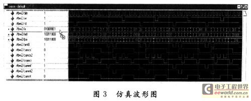
The module was synthesized in Xilinx ISE 9.1 and functionally simulated in ModelSim environment. The simulation results are shown in Figure 3.

3 Software Design
The key to the system software design is the communication program design. The communication software consists of three parts: the initialization program of the microcontroller and the CAN controller, the CAN sending program, and the CAN receiving program. For the initialization program, the MAX232 chip is used to program the microcontroller online, and the multi-channel CAN controller can be initialized at the same time. For the initialization program of the CAN controller, the working mode of the CAN controller is determined mainly by writing control words to the registers in the control segment of the CAN controller, that is, a reset request is sent to the CAN controller through power-on reset, hardware reset or software reset, and then the initialization can be entered. During the reset, the necessary registers are set. For the sending and receiving programs, it is only necessary to send the incoming information frame to the sending or receiving buffer of the CAN and start the command at the same time. The two can use the query mode or the interrupt mode. For the interrupt mode, the program is divided into two parts: the main program and the interrupt service program. In specific projects, it is necessary to combine software and hardware debugging to ensure that the design of each part is accurate and meets the requirements of actual application.
4 Conclusion
Based on the analysis of CAN communication protocol, a multi-channel real-time CAN bus simulator architecture was constructed, and the correctness of the design was verified through functional simulation using CPLD devices. The actual engineering project proved that the design was feasible and met the requirements of high reliability, high real-time performance and high transmission rate in practical applications.
Previous article:Design of Serial Rapid10 Information Line Communication System Based on C645x
Next article:CAN bus realizes industrial network distributed measurement and control system
- Molex leverages SAP solutions to drive smart supply chain collaboration
- Pickering Launches New Future-Proof PXIe Single-Slot Controller for High-Performance Test and Measurement Applications
- CGD and Qorvo to jointly revolutionize motor control solutions
- Advanced gameplay, Harting takes your PCB board connection to a new level!
- Nidec Intelligent Motion is the first to launch an electric clutch ECU for two-wheeled vehicles
- Bosch and Tsinghua University renew cooperation agreement on artificial intelligence research to jointly promote the development of artificial intelligence in the industrial field
- GigaDevice unveils new MCU products, deeply unlocking industrial application scenarios with diversified products and solutions
- Advantech: Investing in Edge AI Innovation to Drive an Intelligent Future
- CGD and QORVO will revolutionize motor control solutions
- Innolux's intelligent steer-by-wire solution makes cars smarter and safer
- 8051 MCU - Parity Check
- How to efficiently balance the sensitivity of tactile sensing interfaces
- What should I do if the servo motor shakes? What causes the servo motor to shake quickly?
- 【Brushless Motor】Analysis of three-phase BLDC motor and sharing of two popular development boards
- Midea Industrial Technology's subsidiaries Clou Electronics and Hekang New Energy jointly appeared at the Munich Battery Energy Storage Exhibition and Solar Energy Exhibition
- Guoxin Sichen | Application of ferroelectric memory PB85RS2MC in power battery management, with a capacity of 2M
- Analysis of common faults of frequency converter
- In a head-on competition with Qualcomm, what kind of cockpit products has Intel come up with?
- Dalian Rongke's all-vanadium liquid flow battery energy storage equipment industrialization project has entered the sprint stage before production
- Allegro MicroSystems Introduces Advanced Magnetic and Inductive Position Sensing Solutions at Electronica 2024
- Car key in the left hand, liveness detection radar in the right hand, UWB is imperative for cars!
- After a decade of rapid development, domestic CIS has entered the market
- Aegis Dagger Battery + Thor EM-i Super Hybrid, Geely New Energy has thrown out two "king bombs"
- A brief discussion on functional safety - fault, error, and failure
- In the smart car 2.0 cycle, these core industry chains are facing major opportunities!
- The United States and Japan are developing new batteries. CATL faces challenges? How should China's new energy battery industry respond?
- Murata launches high-precision 6-axis inertial sensor for automobiles
- Ford patents pre-charge alarm to help save costs and respond to emergencies
- New real-time microcontroller system from Texas Instruments enables smarter processing in automotive and industrial applications
- The development history of single-chip microcomputer and 51 series single-chip microcomputer
- A brief discussion on the 9 functions and 27 applications of capacitors in power supplies
- I want a dsp audio tuning software. If there is a project that can be developed, you can take a look.
- Principle and application of sound sensor
- What is the difference between Solder Mask and Paste Mask?
- Xiaomi Mijia Electric Toothbrush Disassembly
- Blood pressure monitor principle
- EEWORLD University ---- Fuse types and tests
- 【New Year's Festival Competition】Photo Summary
- [Littelfuse Live Review] SiC MOSFET and Schottky Diode Product Introduction and Related Applications (including PPT, QA)

 Hardware Security Attack and Defense Revealed
 SensorSimII is the framework of a simulator that I have been working on to study how future sensor n


 京公网安备 11010802033920号