The horizon is a key subsystem of the satellite attitude control system, and its measurement accuracy and reliability are directly related to whether the satellite attitude is accurate and stable. This paper uses TI's DSP chip TMS320C6711B (C6711 for short) to implement the center positioning algorithm.
1 Hardware composition of real-time image processing system
This system is based on C6711, assisted by field programmable gate array FPGA and high-speed A/D devices to form a real-time high-speed digital image processing system. The system hardware block diagram is shown in Figure 1. The working principle of the image processing system is: the analog image signal output by CCD acquisition is converted into a digital signal through high-speed A/D. Under the control of FPGA, the digital image signal continuously inputs data into the dual-port RAM. Whenever a frame of image scanning is completed, FPGA provides an interrupt flag signal to trigger DSP to move data and move a frame of image in the dual-port RAM to SDRAM through C6711's QDMA. After QDMA moves the data, it checks whether the image data is valid. If it is valid, it triggers DSP to execute the image processing program, otherwise it returns and waits for the next interrupt to arrive. Before the next interrupt arrives, DSP processes the current frame of image, outputs the obtained attitude angle information to the RS232 port of the PC through the multi-channel buffered serial port McBSP and displays it, and then enters the interrupt waiting state, waiting for the interrupt to trigger QDMA again to move data.
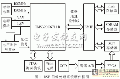
1.1 C6711 Digital Signal Processor
C6711 is a high-speed floating-point DSP chip from TI, with a main frequency of 150MHz and a peak computing capacity of up to 900MFLOPS. C6711 consists of three parts: CPU core, on-chip peripherals and memory. The processing unit adopts high-performance, advanced VelociTITM structure, and 8 functional units can work in parallel per clock cycle. C6711 has the following characteristics that are particularly suitable for real-time image processing:
(1) Advanced VelociTI VLIW C67xDSP core;
(2) Hardware supports IEEE standard single-precision and double-precision floating-point instructions;
(3) 32-bit external memory interface (EMIF), providing seamless interface with synchronous and asynchronous memories;
(4) Two-level cache structure, including: program cache 32Kbit, data cache 32Kbit, and secondary cache 512Kbit;
(5) Enhanced DMA controller, a total of 16 independent channels.
1.2 A/D conversion
The analog image signal output by the CCD is converted into a 10-bit digital image signal through a high-speed A/D, and is stored in a dual-port RAM memory under the control of the FPGA for use in DSP processing.
1.3 Power module and monitoring reset circuit
The C6000 series DSP requires two voltages, namely the CPU core voltage and the peripheral I/O interface voltage. The C6711 requires two voltages, 3.3V and 1.8V, and requires the two power supplies to meet a certain power-on sequence. This system adopts the method of powering on both at the same time. According to the power consumption requirements of the system, the chips TPS5431 6 and TPS54314 are used to directly generate 3.3V and 1.8V voltages, which can provide a maximum power supply current of 3A. The power supply monitoring and reset circuit is implemented using TI's TPS3307-33, which can monitor three independent voltages of 3.3V/5V/1.8V at the same time, and when one of the three monitored voltages is lower than its threshold value, it can ensure the output is valid.
signal, resets the DSP, and when their values are higher than the threshold,
The signal becomes high level.
1.4 Clock module and JTAG interface
The 25MHz clock signal is multiplied by ICS501 to generate 150MHz and 100MHz clock signals, which are output by the three-state gate bus buffer 74LVTH125 to obtain the CPU working clock and the working clock required by the synchronous interface.
, TMS, TDI, TDO, TCK, EMU1 and EMU0 are connected to a 14-pin double-row header, which can be connected to the emulator for system debugging and program downloading.
1.5 External Memory Design
C6711 must access external memory through EMIF. EMIF not only has a high data throughput rate, but also has strong interface capabilities, and can directly interface with all types of current memory. The design uses three types of memory: Flash ROM, dual-port RAM, and synchronous dynamic memory SDRAM. Flash ROM is a memory that can be erased on site and can retain data after power failure. It is used to solidify programs and save data that needs to be saved after power failure; dual-port RAM is used to store a frame of image data; SDRAM runs fast and is used to store real-time running programs and temporary data. The Flash ROM of this system uses SST39VF040 and is configured in CE1 space. The dual-port RAM uses IDT70V28 and is configured in CE2 space. HY57V653220 is selected as SDRAM and configured in CE0 space. This configuration is compatible with the boot mode.
1.6 Output Circuit
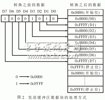
The system processes the input image and obtains satellite attitude angle information after processing by C6711. The attitude angle information is output by C6711 to the RS-232 port of the PC. Since the amount of information in the communication is small, the multi-channel buffered serial port McBSP of C6711 can be used to implement the asynchronous data transmission format by software without expanding other hardware. When sending, the sending conversion subroutine expands each data bit into a 16-bit UART word and puts these converted data blocks into the sending buffer, while adding the start bit and stop bit at the appropriate place (as shown in Figure 2). Then EDMA transfers the data from the sending buffer to McBSP, and the McBSP frame synchronization generator is responsible for continuously moving out these data [4]; when receiving, EDMA reads the expanded data from McBSP and writes these data into the receiving buffer, and then calls the compression subroutine to convert the data into the original byte form. The advantage of this method is that the hardware interface is simple, and only a level conversion circuit between CMOS level and RS232 level needs to be added.
2 Implementation of image processing algorithm
The design of the center positioning image processing algorithm is based on the input image format of 320×240 pixels and 1024 gray levels/pixel, including filtering, judging whether the horizon circle enters the field of view, edge detection and precise centering.
2.1 Filtering
The detector may have less than 1% bad cells, whose grayscale values are mainly 0 or 1023, and the bad cell area is less than 3×3. The existence of bad cells may cause errors in edge detection. In addition, the signal-to-noise ratio of the collected image data is relatively low, so a two-dimensional median filter is used [5]. The method is as follows: for a frame of image, a 3×3 window is moved from top to bottom and from left to right. At each position, 9 image pixels will appear in the window. The grayscale values of these 9 pixels are sorted, and the pixel value in the middle is found using the quick sort method. This value is assigned to the center pixel of the 3×3 window. This method can effectively filter out sudden interference with an area no larger than 2×2, thereby improving the accuracy of the algorithm.
2.2 Determine whether the horizon enters the field of view
When the satellite initially enters orbit, the earth may not be detected in the initial state of the horizon. At this time, the search program needs to be started to control the satellite deflection to search for the earth. Therefore, the obtained horizon image must be scanned line by line to determine whether the earth enters the field of view.
2.3 Edge Detection
Edge extraction first detects the discontinuity of local characteristics of the image, and then connects these discontinuous edge pixels into a complete boundary. The characteristic of an edge is that the pixels along the edge change slowly, while the pixels perpendicular to the edge change dramatically. In this sense, the algorithm for extracting the edge is a mathematical operator that detects edge pixels that meet the edge characteristics.
Since the radiation of the earth is not uniform, the horizon height is related to the horizon detection method used. The difference lies in that the specific horizon height varies with the earth's radiation to different degrees for different horizon detection methods. This paper uses the proportional threshold method to detect the horizon circle. The specific algorithm is as follows: starting from the rough center of the earth, 720 rays are taken at intervals of 0.5 degrees. Considering that only the earth's radiation transition zone needs to be scanned, the scanning starting point of each ray is 100 units away from the rough center of the earth, and sampling is performed once every unit. Since the coordinates of the sampling point are not integers, bilinear interpolation is used to obtain the grayscale value of the sampling point, and the sampling points are judged in turn, while recording the maximum grayscale value and judging whether the grayscale value is less than half of the maximum value. When the condition is met, the scanning stops, and the coordinates corresponding to the grayscale value of 50% of the maximum value are calculated, that is, the coordinates of the horizon point. After scanning 720 rays, all the horizon points constitute a horizon circle. The algorithm performs bilinear interpolation on points close to the transition zone, which improves the efficiency of program execution. The detected coordinates of the horizon point are floating point numbers, which improves the accuracy of horizon determination and helps reduce the error in measuring the center of the earth.
2.4 Accurate centering
Accurate center determination is the most critical part of the algorithm. The quality of the method directly affects the accuracy of the center of the earth. Generally, there are Hough transform method, area integration and three-point mean method. The area integration method is used for accurate positioning. According to the theory of calculus, for a closed area D, its center of gravity coordinates can be obtained using the following formula:
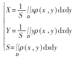
Where x and y represent the coordinates of the unit point, ρ(x, y) represents the density of the unit point, and D represents the entire area.
When ρ(x, y)=1, the centroid and centroid of the region coincide, and S represents the area of the region. In order to calculate the center position of the region using a computer, the above formula must be discretized. The discretized formula is:
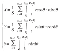
Where R(θ) represents the amplitude variation law within the range of θi~θi+1.
3 Experimental Results
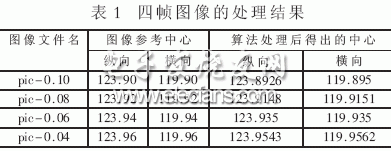
The image data captured by the CCD is sent to the system for processing. After processing each frame of the image, an attitude angle information is output from the serial port. Table 1 shows the processing results of four frames of images. From Table 1, it can be seen that the accuracy of the algorithm is better than the index requirement of 0.1, and the algorithm processing time is about 0.49 seconds, which meets the real-time requirement of processing one frame per second.
The real-time image processing system realizes image acquisition, real-time data processing and output. The system has good upgradeability and scalability. The use of DSP processor enhances the processing capability of the system, improves the system processing speed, and ensures the real-time requirements of the work. The use of surface mount devices not only reduces the size of the PCB board, but also enhances the reliability of the system. Experiments have shown that the center positioning algorithm greatly improves the measurement accuracy of the horizon instrument by filtering the original image, judging whether the target enters the field of view, edge detection and accurate centering.
Previous article:Optimizing Industrial Control with ARM Architecture Processors
Next article:Realization of HPI Interface between TMS320VC5402 DSP and Single Chip Microcomputer
- Molex leverages SAP solutions to drive smart supply chain collaboration
- Pickering Launches New Future-Proof PXIe Single-Slot Controller for High-Performance Test and Measurement Applications
- CGD and Qorvo to jointly revolutionize motor control solutions
- Advanced gameplay, Harting takes your PCB board connection to a new level!
- Nidec Intelligent Motion is the first to launch an electric clutch ECU for two-wheeled vehicles
- Bosch and Tsinghua University renew cooperation agreement on artificial intelligence research to jointly promote the development of artificial intelligence in the industrial field
- GigaDevice unveils new MCU products, deeply unlocking industrial application scenarios with diversified products and solutions
- Advantech: Investing in Edge AI Innovation to Drive an Intelligent Future
- CGD and QORVO will revolutionize motor control solutions
- Innolux's intelligent steer-by-wire solution makes cars smarter and safer
- 8051 MCU - Parity Check
- How to efficiently balance the sensitivity of tactile sensing interfaces
- What should I do if the servo motor shakes? What causes the servo motor to shake quickly?
- 【Brushless Motor】Analysis of three-phase BLDC motor and sharing of two popular development boards
- Midea Industrial Technology's subsidiaries Clou Electronics and Hekang New Energy jointly appeared at the Munich Battery Energy Storage Exhibition and Solar Energy Exhibition
- Guoxin Sichen | Application of ferroelectric memory PB85RS2MC in power battery management, with a capacity of 2M
- Analysis of common faults of frequency converter
- In a head-on competition with Qualcomm, what kind of cockpit products has Intel come up with?
- Dalian Rongke's all-vanadium liquid flow battery energy storage equipment industrialization project has entered the sprint stage before production
- Allegro MicroSystems Introduces Advanced Magnetic and Inductive Position Sensing Solutions at Electronica 2024
- Car key in the left hand, liveness detection radar in the right hand, UWB is imperative for cars!
- After a decade of rapid development, domestic CIS has entered the market
- Aegis Dagger Battery + Thor EM-i Super Hybrid, Geely New Energy has thrown out two "king bombs"
- A brief discussion on functional safety - fault, error, and failure
- In the smart car 2.0 cycle, these core industry chains are facing major opportunities!
- The United States and Japan are developing new batteries. CATL faces challenges? How should China's new energy battery industry respond?
- Murata launches high-precision 6-axis inertial sensor for automobiles
- Ford patents pre-charge alarm to help save costs and respond to emergencies
- New real-time microcontroller system from Texas Instruments enables smarter processing in automotive and industrial applications
- EEWORLD大学堂----Modern Robotics: Mechanics, Planning, and Control
- Microcontroller Basics
- Which PCB teaching video is more reliable?
- STM32 pin short circuit to ground analysis
- DSP core + coprocessor
- [Zero-knowledge ESP8266 tutorial] Advanced 3 SSDP Simple Service Discovery Protocol
- DC 48V60V72V85V to 5V2A 12V2A switching power supply circuit
- SST25 series memory architecture issues
- Working conditions of three states of circuit
- EEWORLD University Hall----2022 Digi-Key KOL Series: Teensy - 1GHz MCU

 Serial Communication Extension Method Based on TMS320C6000


 京公网安备 11010802033920号