With the rapid development of the information industry, the performance requirements for A/D and D/A are getting higher and higher. At present, research on high-speed and high-precision ADC is very active. The sampling clock is a basic element of the ADC conversion circuit. For circuit designers, the clock scheme, clock type, clock voltage level, and clock jitter used in the ADC clock circuit are all issues that must be considered in actual circuit design. The jitter of the sampling clock is a short-term, non-accumulative variable that represents the time deviation between the actual timing position of the digital signal and its ideal position. Clock jitter can cause the internal circuit of the ADC to trigger the sampling time incorrectly, resulting in the mis-sampling of the analog input signal in amplitude, thereby deteriorating the signal-to-noise ratio of the ADC. The impact of the sampling clock jitter on the performance of high-speed and high-precision ADCs cannot be ignored [1-2].
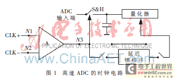
Figure 1 shows a typical ADC clock circuit. High-speed ADCs, such as
ADS5500
, often use this clock structure. This article analyzes the impact of the parameters of the internal clock on the ADC performance based on the clock circuit shown in Figure 1. The analysis results provide a reference for the design of external clock circuits.

1 Relationship between jitter and Ain, fin, fS
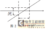
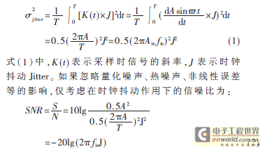
Before the clock signal starts the sample-and-hold circuit for sampling, the internal switch of the sample-and-hold circuit is in a closed state, and the capacitor voltage tracks the changes of the analog input signal. When an edge of the clock signal arrives, the switch opens, and the capacitor voltage remains at the value at that moment. As shown in Figure 2, the voltage value at that moment is the value corresponding to the vertical dotted line. During the sampling time of Δt, a sampling voltage error ΔV is generated. This instantaneous error is the clock jitter Jitter, and the magnitude of the sampling voltage error depends on the input voltage waveform. If there are no other noise signals, the magnitude of the jitter voltage and the signal-to-noise ratio can be calculated according to Figure 2. If the input signal of Figure 1 is a sine wave with an amplitude of Ain and a frequency of fin, the clock jitter Jitter of the sampling voltage is proportional to the slope of the input voltage at that moment and the sampling time. Then the square of the effective value of the clock jitter Jitter of one cycle δ2 is:


From equation (2), we can see that the signal-to-noise ratio caused by clock jitter is related to the frequency fin of the input signal. As the frequency fin of the input signal increases, the signal-to-noise ratio decreases. It can also be seen that the signal-to-noise ratio caused by clock jitter is independent of the input signal amplitude Ain. However, as can be seen from Figure 2, as the input signal amplitude Ain decreases, the clock jitter Jitter decreases accordingly. Therefore, the signal-
to-noise ratio is closely related to the clock jitter Jitter.
The total noise of the ADC consists of three parts: thermal noise, quantization noise, and jitter. If it is assumed that all noise sources are linearly independent, the signal-to-noise ratio of the ADC can be expressed by equation (3).

In equation (3), T represents the square of the effective value of thermal noise in one cycle, and Q represents the square of the effective value of quantization noise in one cycle. These two items are independent of the frequency fin of the input signal. The square of the effective value of the clock jitter in one cycle δ2 depends on the input signal frequency fin. If the ADC is required to have a high SNR when the input signal fin is large, a sampling clock with small jitter must be used. Therefore, in the design of high-speed and high-precision ADCs, special processing methods are used to reduce clock jitter for the clock circuit, such as Maxim's Max104.
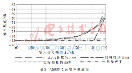
For a certain ADC, when the input signal amplitude Ain is lower than a certain value, its signal-to-noise ratio mainly depends on thermal noise and quantization noise. In this case, clock jitter has little effect on it. Figure 3 shows the actual noise floor of ADS5542 working at 78 MSPS and 230 MHz input. The theoretical curve in Figure 3 is calculated by formula (2) under the condition of adding 250 fs jitter and 1LSB thermal noise. It can be seen from the figure that the theoretical curve is very close to the actual measured noise floor curve. Table 1 shows the size of the signal-to-noise ratio at different input signal frequencies. The table gives two sets of data, one for the actual measured signal-to-noise ratio SNR, and one for the signal-to-noise ratio SNR calculated by formula (2). The measured values in Table 1 are measured under the condition of sampling frequency fs of 60 MS/s and assuming that the jitter frequency is 200 fs. It can be seen from Table 1 that the error between the data estimated by formula (2) and the actual measured data is small, and formula (2) accurately expresses the relationship between the signal-to-noise ratio and the input signal frequency.


From the research results of reference [4], it can be seen that when the sampling frequency fs remains unchanged, the signal-to-noise ratio will decrease as the frequency of the input signal increases. If the input sinusoidal signal itself is not affected by noise, the decrease in the signal-to-noise ratio is caused by clock jitter.
From equation (2), it can be seen that the signal-to-noise ratio is independent of the sampling frequency. However, experimental data show that when the sampling frequency increases, the signal-to-noise ratio also increases. This is because the increase in sampling frequency will spread the same amount of noise to a wider frequency band, which can effectively reduce the noise floor. However, when actually calculating the signal-to-noise ratio, the total noise also includes thermal noise and quantization noise. Therefore, the research results of reference [4] do not show that the signal-to-noise ratio increases with the increase in sampling frequency [4].
Jitter is a simplification of phase noise. Phase noise that appears in different places has different degrees of influence on the system. Phase noise close to the carrier reflects the slow changes at the sampling moment and is irrelevant to the system in a relatively short observation time. Phase noise far from the carrier has a large impact on the system but is easily filtered out by the filter [5]. At present, some ADCs on the market not only do not provide any solution to block input jitter, but the clock chain inside the ADC makes the jitter worse.
2 Calculation of jitter
The jitter source may come from the outside, such as the clock signal provided by the user, or from the internal clock circuit of the ADC, such as the (N1, N2) and (N3) points of the amplifier. For the jitter originating from the (N1, N2) point in Figure 1, certain measures can be taken to reduce its impact. It can be seen from Figure 2 that this part of the jitter is related to the edge slope of the clock signal. The rising edge of the clock signal is used to turn on the switch of the sample-and-hold device. In theory, the jitter of the falling edge of the clock signal does not affect the signal-to-noise ratio. To simplify the analysis, it is assumed that the slopes of the rising and falling edges of the clock signal are the same.
When the slope of the input clock edge is infinite, any voltage noise added to the edge will not affect the time positioning on the edge. When the slope of the clock edge becomes smaller, adding the voltage noise on the edge will produce a larger time error. When the clock signal is a sine wave signal, increasing the signal amplitude or increasing the sampling frequency can increase the slope of the edge. The total clock jitter can be described by the following equation:

The clock jitter size is calculated by equation (5), and the signal-to-noise ratio calculated by equation (4) is shown in Figure 4. It can be seen that the error between the signal-to-noise ratio value calculated by the above method and the actual measured value is small. Table 2 shows the specific value comparison.


Analyzing Table 2, if the clock uses a sinusoidal signal, the peak-to-peak value of the clock is required to be around 4 V for better results; if a unilateral clock signal is selected, its maximum amplitude is 3.3 Vpp; using a differential clock signal can increase the clock amplitude to twice this value, and can suppress common-mode interference, but the use of a differential clock signal also brings about the symmetry problem of the two edges. From reference [4], it can be seen that the effect of using a unilateral clock signal with a smaller amplitude is better than that of a differential clock signal. The main reason is the asymmetry of the two edges of the differential clock signal, and when the digital output voltage increases, switching noise coupled in the clock circuit will be generated. This effect can be reduced by reducing the input signal frequency.
3 Improvement measures
From the above analysis, it can be seen that to reduce clock jitter, the key is to increase the edge slope of the clock signal and generate a clock signal similar to a square wave. Specifically, it can be started from the following aspects:
(1) Use the step converter method. After the sinusoidal clock signal passes through the step converter, it generates a clock signal similar to a square wave.
(2) Add an external gate circuit as a comparator to square the sinusoidal clock signal. This method can reduce the influence of N1 and N2, but the problem it brings is the balance of N1 and N2 at the input of the comparator. The clock jitter of ADCs on the market is relatively small, but these data are based on the assumption that the input signal is a square wave. If a sinusoidal clock signal is used, the jitter will increase significantly.
(3) Use a low-jitter clock source with a square wave output. For example, use a voltage-controlled crystal oscillator (such as CDC7005). However, the use of this circuit is limited by the phase noise quality of the VCXO and the deterioration added by the CD7005. However, this circuit saves a converter to generate a differential clock.
(4) Adding an external bandpass filter can eliminate the jitter of the clock signal. However, the amplitude attenuation of the filter reduces the amplitude of the clock, reduces the edge slope, and increases the influence of N1 and N2. Therefore, it is necessary to add an amplifier or a step converter in front of the filter to reduce this trend.
This article starts with the parameters of the ADC input signal and clock source, analyzes the impact of the input signal amplitude, frequency, and sampling frequency on clock jitter and ADC signal-to-noise ratio, and gives a method for calculating clock jitter based on the information provided in the ADC manual data. The calculation results are verified, and then a method for reducing clock jitter is proposed. This method of calculating clock jitter does not require an external circuit, and comprehensively considers the impact of various noise sources in the clock circuit. The calculation method is simple and relatively accurate. The research results provide a theoretical basis for ADC external circuit design and ADC selection.
References
[1] Zhao Jiyong, Peng Fei. Low jitter clock design for high speed ADC [J]. Electronic Design Applications, 2005, 4(2): 79-83.
[2] SHINAGAWA M, AKAZAWA Y, WAKIMOTE T, et al. Jitter analysis of high speed sampling
systems [J]. IEEE JSolid2state Circuits, 1990, 25(1): 220-224.
[3] Tang Shiyue, Wang Yanfang, He Zhengmiao. Research on clock jitter test platform based on ADC [J]. Journal of Circuits and Systems, 2008, 13(6): 13-17.
[4] 14 Bit, 125 MSPS Analog-to-Digital Converter [M].
ADS5500
Data Sheet, 13-17.
[5] ZANCHI A, BONFANTI A, LEVANTINO S, et al. General SSCR vs. cycle-to-cycle jitter relationship with application to the phase noise in PLL[J].Proceedings of the 2001 IEEE Southwest Symposium on Mixed-Signal Design, 2001(2):32-37.
[6] ZANCHI A, PAPANTONOPOULOS I, TSAY F.Measurement and Spice prediction of sub-picosecond clock jitter in A/D converters[J].Proceedings of the 2003 IEEE International Symposium on Circuits and Systems, 2003(5): 557-560
Previous article:Research on the virtual signal generation method of a simulator
Next article:How to Enable the ITU-T G.703 2048kHz Synchronous Interface in the DS26303 LIU
- Popular Resources
- Popular amplifiers
- Molex leverages SAP solutions to drive smart supply chain collaboration
- Pickering Launches New Future-Proof PXIe Single-Slot Controller for High-Performance Test and Measurement Applications
- CGD and Qorvo to jointly revolutionize motor control solutions
- Advanced gameplay, Harting takes your PCB board connection to a new level!
- Nidec Intelligent Motion is the first to launch an electric clutch ECU for two-wheeled vehicles
- Bosch and Tsinghua University renew cooperation agreement on artificial intelligence research to jointly promote the development of artificial intelligence in the industrial field
- GigaDevice unveils new MCU products, deeply unlocking industrial application scenarios with diversified products and solutions
- Advantech: Investing in Edge AI Innovation to Drive an Intelligent Future
- CGD and QORVO will revolutionize motor control solutions
- Innolux's intelligent steer-by-wire solution makes cars smarter and safer
- 8051 MCU - Parity Check
- How to efficiently balance the sensitivity of tactile sensing interfaces
- What should I do if the servo motor shakes? What causes the servo motor to shake quickly?
- 【Brushless Motor】Analysis of three-phase BLDC motor and sharing of two popular development boards
- Midea Industrial Technology's subsidiaries Clou Electronics and Hekang New Energy jointly appeared at the Munich Battery Energy Storage Exhibition and Solar Energy Exhibition
- Guoxin Sichen | Application of ferroelectric memory PB85RS2MC in power battery management, with a capacity of 2M
- Analysis of common faults of frequency converter
- In a head-on competition with Qualcomm, what kind of cockpit products has Intel come up with?
- Dalian Rongke's all-vanadium liquid flow battery energy storage equipment industrialization project has entered the sprint stage before production
- Allegro MicroSystems Introduces Advanced Magnetic and Inductive Position Sensing Solutions at Electronica 2024
- Car key in the left hand, liveness detection radar in the right hand, UWB is imperative for cars!
- After a decade of rapid development, domestic CIS has entered the market
- Aegis Dagger Battery + Thor EM-i Super Hybrid, Geely New Energy has thrown out two "king bombs"
- A brief discussion on functional safety - fault, error, and failure
- In the smart car 2.0 cycle, these core industry chains are facing major opportunities!
- The United States and Japan are developing new batteries. CATL faces challenges? How should China's new energy battery industry respond?
- Murata launches high-precision 6-axis inertial sensor for automobiles
- Ford patents pre-charge alarm to help save costs and respond to emergencies
- New real-time microcontroller system from Texas Instruments enables smarter processing in automotive and industrial applications
- EEWORLD University - Learn C language from scratch
- [ESP32-S2-Kaluga-1 Review] 5. Use LGVL to create a low-level interface?
- Why is the voltage ringing spike of MOSFET different in boost and buck mode?
- The circuit for discharging the PFC output capacitor is shown in Figure 2.
- Basic syntax of Verilog HDL
- Found a method to import Altium Designer into SIwave
- Thanks to okhxyyo for searching and fish001 for sharing
- Please advise, is it easy to pass the postgraduate examination and graduate, and how useful is the degree certificate?
- About the LAUNCHXL-F28379D Development Kit
- Let me try this feature

 TL33071D


 京公网安备 11010802033920号