1
Introduction
In order to exploit the heavy oil containing "
three highs
"
such as asphalt, wax and high freezing point
, oil fields usually adopt steam stimulation, chemical viscosity reduction and hot water jet accompaniment. These methods have the disadvantages of high investment and inconvenient management. At present, Jiangsu Oilfield adopts steel hollow sucker rod induction heating technology in combination with its own characteristics when exploiting heavy oil. This technology has the following characteristics: simple equipment, convenient downhole operation and maintenance; adjustable input power; easy to realize automatic control; uniform heating along the way without local overheating; high thermal efficiency (heating in the center of the oil pipe); no fear of power outage and pumping; extended operation cycle; improved production efficiency; no pollution to the environment; safe to use and easy to manage; small one-time investment and fast capital recovery [
1
].
According to the current domestic power supply mode, the hollow sucker rod induction heating system adopts the industrial frequency induction heating method. In order to balance the three-phase power consumption, the industrial frequency heating power supply shifts one phase of the industrial frequency three-phase AC power to the other two phases through the reactor and capacitor series phase shift, and then directly converts it into a single-phase industrial frequency AC power suitable for various heating requirements through the transformer and then connects the heating conductor. Therefore, the industrial frequency heating power supply has high cost, large size, bulky weight and low efficiency.
The petroleum medium-frequency induction heating power supply uses
IGBT
as the inverter switch device. Compared with the commonly used industrial frequency heating power supply, its volume is reduced by
40
% and its weight is reduced by
50
%.
2
Medium frequency induction heating power supply
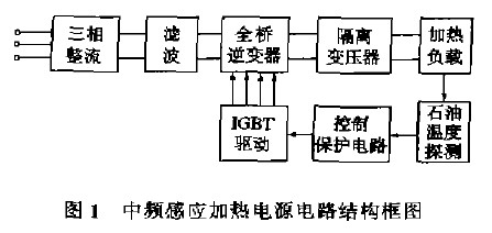
The circuit structure of the medium frequency induction heating power supply is shown in Figure
1.
The three-phase rectifier rectifies the industrial frequency three-phase AC into DC. After filtering, it is converted into a single-phase medium frequency AC with continuously adjustable frequency and duty cycle within a certain range by the full-bridge inverter, and then output to the heating load through the isolation transformer. The full-bridge inverter adopts a pulse width modulation (
PWM
) zero voltage switching circuit, which has the advantages of low switching loss and low electromagnetic interference [
2
]. The control circuit adopts
the SG3524
integrated block to adjust
the voltage of
the 9th
pin to ensure the dead time of the output signal. The pulse width of the output signal is modulated by the oil temperature detector. The temperature of the oil is controlled at
45
~
70℃
. Too high temperature can easily change the chemical properties of the oil. Too low temperature will reduce the fluidity of the oil.

3 IGBT
gate drive circuit
3.1
Selection of
IGBT
gate
drive
module
IGBT
gate drive modules
EXB841
and
M57962L
can be used to drive
IGBT
modules
within
400A
of the
1200V
series
, and have overcurrent detection
and
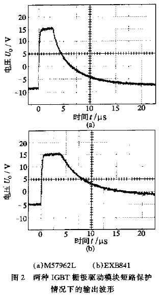
protection functions. The output waveforms of these two drive modules under short-circuit protection
are shown
in Figure
2.
EXB841
generates a
5V
negative bias internally and is not adjustable;
M57962L
uses a voltage-stabilizing diode to generate a
9V
negative bias
externally
, and the gate-off reliability is higher than that
of EXB841
. In addition,
the
protection action time of
M57962L
(from overcurrent to gate voltage dropping to
0V) is 6.3μs
(
see
Figure
2a
)
;
the protection action time of
EXB841
is
16μs
and the gate-off voltage cannot drop
below
-2V
(see Figure
2b
),
which leads to
a greater
risk of
IGBT
explosion
than
M57962L
. Therefore,
M57962L
should be selected
.

3.2
Improvement
of peripheral circuit of driver
module
When
the IGBT
is turned off, the voltage rise rate between the collector and emitter is as high as
30000V
/
μs
. If it is too high, it will produce a large displacement current. It will also lead to a large collector pulse surge current, which can easily cause
the IGBT
to be dynamically locked. In order to avoid
this malfunction of
the IGBT
,
a negative bias must be added
to
the IGBT gate
[
3
]. However, in actual applications, the following two situations will cause the negative bias of the drive circuit to disappear:
①
The voltage regulator diode breaks down and shorts;
②
The drive circuit loses
the
+24V
power supply.
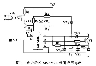
In view of the above two situations, the author improved the peripheral circuit of
the IGBT
driver module
M57962L
based on the manufacturer's recommended application circuit
, as shown in Figure
3.
Under normal circumstances,
VZ4
is turned on,
M57962L⑧
foot is high potential,
VD1
is turned off,
VT2
is turned on,
and the output end
of VO1
is in a low impedance state. If the voltage-stabilizing diode
VZ1
or
VZ3
breaks down and shorts,
VZ4
is turned off,
VT1
is turned off, and
the output end of
VO1
is in a high impedance state. If the driving circuit loses
the
+24V
voltage,
no current flows through the input end
of VO1
, and
the output end of
VO1
is in a high impedance state.

4
Connection between IGBT module and filter capacitor
The input characteristics of
IGBT
are similar to those
of MOSFET
. The input impedance is high. If the drive circuit loses voltage, the gate of
the IGBT
loses negative bias. It is in a high impedance state to the emitter. At this time, once interference reaches
the gate of
the IGBT
, the upper and lower tubes of the
IGBT
module are likely to be turned on at the same time. If
the
IGBT
module is directly connected to a filter capacitor of several thousand microfarads, the energy stored in the filter capacitor will be
directly released through the upper and lower tubes of the
IGBT
module, which may easily cause damage to the
IGBT
module. Therefore, when the induction heating power supply is turned on, the power supply of the control and drive circuits is first connected, and then
the
IGBT
module is connected to the filter capacitor. When shutting down,
the IGBT
module is disconnected from the filter capacitor
first
, and then the power supply of the control and drive circuits is turned off.
5
Test results and conclusions
The induction heating power supply of PetroChina has been tested in the field of the second trial production plant since
June
1997 and is still working normally. The power supply power is
3588kw
.
The
induction heating power supply of PetroChina can not only be used in the hollow sucker rod induction heating system. It can also be used in the medium frequency induction electric heating system of the gathering and transportation pipelines in complex small fault block oil fields, which is of great significance to reducing the infrastructure investment and operation costs of the gathering and transportation pipelines.
Previous article:Application of IGBT high voltage inverter in blast furnace water slag flushing system
Next article:Research on bipolar phase-shift controlled high-frequency pulse AC link inverter
- Popular Resources
- Popular amplifiers
- MathWorks and NXP Collaborate to Launch Model-Based Design Toolbox for Battery Management Systems
- STMicroelectronics' advanced galvanically isolated gate driver STGAP3S provides flexible protection for IGBTs and SiC MOSFETs
- New diaphragm-free solid-state lithium battery technology is launched: the distance between the positive and negative electrodes is less than 0.000001 meters
- [“Source” Observe the Autumn Series] Application and testing of the next generation of semiconductor gallium oxide device photodetectors
- 采用自主设计封装,绝缘电阻显著提高!ROHM开发出更高电压xEV系统的SiC肖特基势垒二极管
- Will GaN replace SiC? PI's disruptive 1700V InnoMux2 is here to demonstrate
- From Isolation to the Third and a Half Generation: Understanding Naxinwei's Gate Driver IC in One Article
- The appeal of 48 V technology: importance, benefits and key factors in system-level applications
- Important breakthrough in recycling of used lithium-ion batteries
- Innolux's intelligent steer-by-wire solution makes cars smarter and safer
- 8051 MCU - Parity Check
- How to efficiently balance the sensitivity of tactile sensing interfaces
- What should I do if the servo motor shakes? What causes the servo motor to shake quickly?
- 【Brushless Motor】Analysis of three-phase BLDC motor and sharing of two popular development boards
- Midea Industrial Technology's subsidiaries Clou Electronics and Hekang New Energy jointly appeared at the Munich Battery Energy Storage Exhibition and Solar Energy Exhibition
- Guoxin Sichen | Application of ferroelectric memory PB85RS2MC in power battery management, with a capacity of 2M
- Analysis of common faults of frequency converter
- In a head-on competition with Qualcomm, what kind of cockpit products has Intel come up with?
- Dalian Rongke's all-vanadium liquid flow battery energy storage equipment industrialization project has entered the sprint stage before production
- Allegro MicroSystems Introduces Advanced Magnetic and Inductive Position Sensing Solutions at Electronica 2024
- Car key in the left hand, liveness detection radar in the right hand, UWB is imperative for cars!
- After a decade of rapid development, domestic CIS has entered the market
- Aegis Dagger Battery + Thor EM-i Super Hybrid, Geely New Energy has thrown out two "king bombs"
- A brief discussion on functional safety - fault, error, and failure
- In the smart car 2.0 cycle, these core industry chains are facing major opportunities!
- The United States and Japan are developing new batteries. CATL faces challenges? How should China's new energy battery industry respond?
- Murata launches high-precision 6-axis inertial sensor for automobiles
- Ford patents pre-charge alarm to help save costs and respond to emergencies
- New real-time microcontroller system from Texas Instruments enables smarter processing in automotive and industrial applications
- How to generate a trapezoidal waveform using TINA-TI?
- C language uses binary tree to parse polynomials and evaluate
- Has anyone used the air quality sensor of the rsl10-sense-gevk board?
- Sound interference gyroscope experiment three ultrasonic interference
- Free evaluation - Topmicro intelligent display module (4) displays Chinese characters
- nand flash interface switch
- Please tell me about the LCD controller of RL78
- Generation of IP cores in FPGA
- Electronics Engineer (FPGA)
- [National Technology N32G430] 4. Make a simple and easy-to-use multi-task scheduling system

 Frequency Converter Circuit Maintenance and Fault Example Analysis


 京公网安备 11010802033920号