1. Introduction
Insulated Gate Bipolar Tramistor (IGBT) is a composite device of MOSFET and GTR. Therefore, it has the advantages of MOSFET, such as fast working speed, high switching frequency, high input impedance, simple driving circuit, and good thermal temperature resistance, and also has many advantages of GTR, such as large current carrying capacity and high blocking voltage. It is an ideal switching device to replace GTR. IGBT is a widely used device with self-shutdown capability, which is widely used in various solid-state power supplies. The working state of IGBT directly affects the performance of the whole machine, so a reasonable driving circuit is very important to the whole machine, but if it is not properly controlled, it is easy to be damaged. One of them is that overcurrent occurs and the IGBT is damaged. This paper mainly studies the driving and short-circuit protection of IGBT, analyzes its working principle, designs a driving circuit with overcurrent protection function, and conducts simulation research.
2. IGBT drive requirements and overcurrent protection analysis
1 IGBT drive
IGBT is a voltage-type control device. In order to enable IGBT to be turned on and off safely and reliably, its drive circuit must meet the following conditions:
The gate capacitance of IGBT is much larger than that of VMOSFET, so to increase its switching speed, it is necessary to have appropriate gate forward and reverse bias voltages and gate series resistance.
(1) Gate voltage
In any case, the gate drive voltage in the on state cannot exceed the limit value given in the parameter table (usually 20V), and the optimal gate forward bias voltage is 15V ± 10%. This value is enough to make the IGBT saturated and turned on, and minimize the conduction loss. Although the IGBT can be in the off state when the gate voltage is zero, in order to reduce the turn-off time and improve the IGBT's withstand voltage, dv/dt tolerance and anti-interference ability, a -5~-15V reverse voltage can be added between the gate and the source when the IGBT is in the blocking state.
(2) Gate series resistance
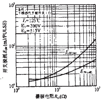
Selecting a suitable gate series resistor Rg is very important for driving the IGBT. The effect of Rg on switching loss is shown in Figure 1.

Figure 1 Effect of Rg on switching loss
The input impedance of IGBT is as high as 109~1011. It does not require DC current in static state. It only needs dynamic current to charge and discharge the input capacitor. Its DC gain can reach 108~109, and it consumes almost no power. In order to improve the steepness of the leading and trailing edges of the control pulse and prevent oscillation, and reduce the voltage spike pulse with extremely large collector of IGBT, it is necessary to connect the gate series resistor Rg. When Rg increases, the on-off time of IGBT will be prolonged, and the energy consumption will increase; while reducing RF will increase di/dt, which may damage IGBT. Therefore, the appropriate Rg should be selected according to the different current capacity, voltage rating and switching frequency of IGBT. Generally, the core value is tens of ohms to hundreds of ohms. When selecting Rg specifically, refer to the user manual of the device.
(3) Driving power requirements
The switching process of IGBT consumes a certain amount of power from the driving power supply. The difference between the positive and negative gate bias voltages is △Vge, the operating frequency is f, and the gate capacitance is Cge. The minimum peak current of the power supply is:
![]()
The average power of the driving power supply is:
![]()
1. Introduction
Insulated Gate Bipolar Tramistor (IGBT) is a composite device of MOSFET and GTR. Therefore, it has the advantages of MOSFET, such as fast working speed, high switching frequency, high input impedance, simple driving circuit, and good thermal temperature resistance, and also has many advantages of GTR, such as large current carrying capacity and high blocking voltage. It is an ideal switching device to replace GTR. IGBT is a widely used device with self-shutdown capability, which is widely used in various solid-state power supplies. The working state of IGBT directly affects the performance of the whole machine, so a reasonable driving circuit is very important to the whole machine, but if it is not properly controlled, it is easy to be damaged. One of them is that overcurrent occurs and the IGBT is damaged. This paper mainly studies the driving and short-circuit protection of IGBT, analyzes its working principle, designs a driving circuit with overcurrent protection function, and conducts simulation research.
2. IGBT drive requirements and overcurrent protection analysis
1 IGBT drive
IGBT is a voltage-type control device. In order to enable IGBT to be turned on and off safely and reliably, its drive circuit must meet the following conditions:
The gate capacitance of IGBT is much larger than that of VMOSFET, so to increase its switching speed, it is necessary to have appropriate gate forward and reverse bias voltages and gate series resistance.
(1) Gate voltage
In any case, the gate drive voltage in the on state cannot exceed the limit value given in the parameter table (usually 20V), and the optimal gate forward bias voltage is 15V ± 10%. This value is enough to make the IGBT saturated and turned on, and minimize the conduction loss. Although the IGBT can be in the off state when the gate voltage is zero, in order to reduce the turn-off time and improve the IGBT's withstand voltage, dv/dt tolerance and anti-interference ability, a -5~-15V reverse voltage can be added between the gate and the source when the IGBT is in the blocking state.
(2) Gate series resistance
Selecting a suitable gate series resistor Rg is very important for driving the IGBT. The effect of Rg on switching loss is shown in Figure 1.

Figure 1 Effect of Rg on switching loss
The input impedance of IGBT is as high as 109~1011. It does not require DC current in static state. It only needs dynamic current to charge and discharge the input capacitor. Its DC gain can reach 108~109, and it consumes almost no power. In order to improve the steepness of the leading and trailing edges of the control pulse and prevent oscillation, and reduce the voltage spike pulse with extremely large collector of IGBT, it is necessary to connect the gate series resistor Rg. When Rg increases, the on-off time of IGBT will be prolonged, and the energy consumption will increase; while reducing RF will increase di/dt, which may damage IGBT. Therefore, the appropriate Rg should be selected according to the different current capacity, voltage rating and switching frequency of IGBT. Generally, the core value is tens of ohms to hundreds of ohms. When selecting Rg specifically, refer to the user manual of the device.
(3) Driving power requirements
The switching process of IGBT consumes a certain amount of power from the driving power supply. The difference between the positive and negative gate bias voltages is △Vge, the operating frequency is f, and the gate capacitance is Cge. The minimum peak current of the power supply is:
![]()
The average power of the driving power supply is:
![]()
2 IGBT overcurrent protection
The overcurrent protection of IGBT is that when the upper and lower bridge arms are directly connected, the power supply voltage is almost entirely applied to both ends of the switch tube, which will generate a large short-circuit current. The smaller the saturation voltage drop of the IGBT, the greater the current will be, thus damaging the device. When the device has an overcurrent, the short-circuit current and its I-V operating trajectory when it is turned off are limited to the short-circuit safe working area of the IGBT, which is used to turn off the IGBT before the device is damaged to avoid damage to the switch tube.
3 Analysis of IGBT drive and overcurrent protection circuit
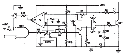
According to the above analysis, this design proposes an IGBT drive circuit with optocoupler isolation and overcurrent protection function, as shown in Figure 2.

Figure 2 IGBT drive and overcurrent protection circuit
In Figure 2, the high-speed optocoupler 6N137 realizes the electrical isolation of input and output signals, which can achieve good electrical isolation and is suitable for high-frequency applications. The main driving circuit adopts a push-pull output mode, which effectively reduces the output impedance of the driving circuit and improves the driving ability, making it suitable for driving high-power IGBTs. The overcurrent protection circuit uses the principle of desaturation of the collector to promptly shut down the IGBT when overcurrent occurs, where V1, V3, and V4 constitute a driving pulse amplification circuit. V1 and R5 constitute an emitter follower, which provides a fast current source and reduces the turn-on and turn-off time of the power tube. Using the collector desaturation principle, D1, R6, R7, and V2 constitute a short-circuit signal detection circuit. D1 uses a fast recovery diode to prevent the high voltage on the collector of the IGBT from entering the driving circuit when it is turned off. In order to prevent static electricity from mis-turning the power device on, bidirectional voltage regulators D3 and D4 are connected in parallel between the gate source. Such as the gate series resistor of the IGBT.
During normal operation:
When the control circuit sends a high-level signal, the optocoupler 6N137 is turned on, V1 and V2 are turned off, V3 is turned on and V4 is turned off. The drive circuit provides a +15V drive start voltage to the IBGT to turn on the IGBT.
When the control circuit sends a low level signal, the optocoupler 6N137 is turned off, VI and V2 are turned on, V4 is turned on and V3 is turned off, and the drive circuit provides a -5V voltage to the IBGT to turn off the IGBT.
When overcurrent occurs:
When a short circuit occurs in the circuit, the upper and lower bridges are directly connected. At this time, the +15V voltage is almost entirely applied to the IGBT. A large current is generated. At this time, v2 is cut off in the short circuit signal detection circuit. The potential of point A depends on the voltage division of D1, R6, R7 and Vces. When the main circuit works normally and the IGBT is turned on, point A remains low, which is lower than the potential of point B. All A1 outputs a low level. At this time, V5 is cut off, and point C is a high level, so when working normally. The signal input to the optocoupler 6N137 is always consistent with the output. When an overcurrent occurs, the IGBT collector desaturates, and the potential of point A rises. When it is higher than the potential of B (that is, the set potential), that is, when the current exceeds the designed fixed value, A1 flips and outputs a high level, and V5 is turned on, thereby clamping the potential of point C in a low potential state, so that the AND gate 4081 always outputs a low level, that is, no matter whether the control circuit sends a high level or a low level, the signal input to the optocoupler 6N137 is always a low level, thereby turning off the power tube. Thus, over-current protection is achieved. The circuit is restarted after the circuit fault is eliminated.
4 Simulation and Experiment
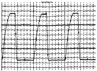
The simulation graphics of this design circuit in orCAD software are as follows:
Input a square wave signal with a high level of +15v and a low level of -5v to the drive circuit. The output waveform of the IGBT is shown in Figure 3:

Figure 3 IGBT output signal
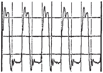
According to the previous principles and analysis, the actual circuit output waveform of the circuit is shown in Figure 4:

Figure 4 Actual circuit output waveform
5 Conclusion
(1) The drive circuit can provide +15V and -5V drive voltages for the IGBT to ensure the on and off of the IGBT.
(2) It has an overcurrent protection function. When overcurrent occurs, the protection circuit will work and shut down the IGBT in time to prevent IGBT damage.
(3) This circuit can dynamically adjust the maximum current according to the needs of the load and can have a wide range of uses.
(4) This design uses discrete components to form the drive circuit, reducing the cost of the entire system.
Previous article:Research on a novel power factor correction chip with critical current conduction
Next article:Application of IGBT in Uninterruptible Power Supply (UPS)
Recommended ReadingLatest update time:2024-11-16 16:20
![[Practical sharing] Detailed explanation of high-voltage CV test of MOSFET devices](https://6.eewimg.cn/news/statics/images/loading.gif)


- Popular Resources
- Popular amplifiers
- MathWorks and NXP Collaborate to Launch Model-Based Design Toolbox for Battery Management Systems
- STMicroelectronics' advanced galvanically isolated gate driver STGAP3S provides flexible protection for IGBTs and SiC MOSFETs
- New diaphragm-free solid-state lithium battery technology is launched: the distance between the positive and negative electrodes is less than 0.000001 meters
- [“Source” Observe the Autumn Series] Application and testing of the next generation of semiconductor gallium oxide device photodetectors
- 采用自主设计封装,绝缘电阻显著提高!ROHM开发出更高电压xEV系统的SiC肖特基势垒二极管
- Will GaN replace SiC? PI's disruptive 1700V InnoMux2 is here to demonstrate
- From Isolation to the Third and a Half Generation: Understanding Naxinwei's Gate Driver IC in One Article
- The appeal of 48 V technology: importance, benefits and key factors in system-level applications
- Important breakthrough in recycling of used lithium-ion batteries
- Innolux's intelligent steer-by-wire solution makes cars smarter and safer
- 8051 MCU - Parity Check
- How to efficiently balance the sensitivity of tactile sensing interfaces
- What should I do if the servo motor shakes? What causes the servo motor to shake quickly?
- 【Brushless Motor】Analysis of three-phase BLDC motor and sharing of two popular development boards
- Midea Industrial Technology's subsidiaries Clou Electronics and Hekang New Energy jointly appeared at the Munich Battery Energy Storage Exhibition and Solar Energy Exhibition
- Guoxin Sichen | Application of ferroelectric memory PB85RS2MC in power battery management, with a capacity of 2M
- Analysis of common faults of frequency converter
- In a head-on competition with Qualcomm, what kind of cockpit products has Intel come up with?
- Dalian Rongke's all-vanadium liquid flow battery energy storage equipment industrialization project has entered the sprint stage before production
- Allegro MicroSystems Introduces Advanced Magnetic and Inductive Position Sensing Solutions at Electronica 2024
- Car key in the left hand, liveness detection radar in the right hand, UWB is imperative for cars!
- After a decade of rapid development, domestic CIS has entered the market
- Aegis Dagger Battery + Thor EM-i Super Hybrid, Geely New Energy has thrown out two "king bombs"
- A brief discussion on functional safety - fault, error, and failure
- In the smart car 2.0 cycle, these core industry chains are facing major opportunities!
- The United States and Japan are developing new batteries. CATL faces challenges? How should China's new energy battery industry respond?
- Murata launches high-precision 6-axis inertial sensor for automobiles
- Ford patents pre-charge alarm to help save costs and respond to emergencies
- New real-time microcontroller system from Texas Instruments enables smarter processing in automotive and industrial applications
- After more than two months of hard work, it is finally finished. Haha
- Live Review: Renesas Electronics R-Car Advanced Driver Assistance System Solution
- TI CC2531 USB Evaluation Module Kit
- Lantern with capacitive touch support
- TI's active equalization solution
- After the ZIGBEE3.0 online seminar this morning, have you DIYed a home automation control system?
- Overcome last-minute requirement changes with small, leaded SOT-23 thin multiplexers
- Where can I find older ICs?
- Make ADAS technology more popular in vehicles
- What is a hysteresis comparator?

 Modern arc welding power supply and its control


 京公网安备 11010802033920号