1. Complex electronic environment
The power supply environment of automotive, industrial and avionics equipment is very complex. To operate in such a harsh power supply environment, it is necessary to have the ability to resist various surge damages. Taking the automotive electronic system power supply application as an example, the system not only needs to meet high reliability requirements, but also needs to deal with relatively unstable battery voltage, which is challenging. The differences in the electronic and mechanical systems connected to the vehicle battery may also cause a large voltage deviation in the nominal 12 V power supply.
In reality, over a period of time, the 12 V supply can vary from –14 V to +35 V, and can experience voltage spikes of +150 V to –220 V. Such high transient voltages are common in automotive and industrial systems and can last from microseconds to hundreds of milliseconds, which carries a huge amount of energy. Some of these surges and transients occur in everyday use, while others are caused by malfunctions or human error.
Regardless of the cause, the damage they cause to automotive electronic systems is difficult to diagnose and expensive to repair. To avoid the risk of failure, the electronics within the system must either be built to withstand these surges or be carefully protected.

Figure 1 Common surge forms in industrial sites
2. Traditional coping methods
Traditional overvoltage (OV) and overcurrent (OC) protection systems often include: capacitors and inductors for filtering low-energy spikes, transient voltage suppressors (TVS) for overvoltage protection, fuses for DC overcurrent protection, series diodes for battery reverse protection, etc.

Figure 2 Traditional protection architecture
Although these devices are improving, these discrete solutions are bulky, imprecise, and can blow fuses during sustained faults, potentially causing wider downtime and failures such as:
(1) To absorb the same amount of energy, discrete devices require a larger volume.
(2) Parameter discreteness. For example, the Zener breakdown voltage of a 78V TVS in the SMB package can range up to 1V.
(3) Continuous or DC transients may blow the fuse or TVS, requiring manual repair.
(4) A diode connected in series in the power path for reverse protection will increase losses and cause heat problems.
3. ADI’s innovative technology – SURGE STOPPER
Alex Yang, an engineer from the technical authorized agent Excelpoint, introduced ADI’s innovative technology - SURGE STOPPER. What functions can SURGE STOPPER achieve?

Figure 3 Application of surge suppressor in automobiles
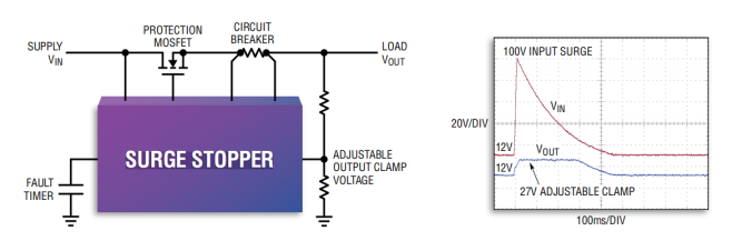
The core of its function is to protect the electronic system at the load end from high voltage shock. And when the surge is applied to the front end of the system, it can ensure the uninterrupted operation of the system. When the front-end power supply of the system has a continuous or DC fault, it can disconnect the load until the front-end power supply returns to normal and the protection system automatically restores power supply. On the other hand, if there is a fault in the back stage, such as overload and short circuit, then SURGE STOPPER can also protect the front-end power supply from being dragged down by the faulty load, and can cleanly cut off the fault channel until it returns to normal.
On the basis of realizing the core functions, SURGE STOPPER considers many details in the design. For example, engineers can fine-tune the clamping voltage with high precision, without having to passively select the device closest to their needs from the TVS selection table. This not only facilitates engineers to change and iterate their designs, but also minimizes over-design and reduces costs.
According to market demand, ADI has innovatively developed three types of products for surge problems, including linear surge suppressors, switching surge suppressors, and protection controllers. In addition, ADI is still constantly trying to solve surge problems with new ideas.
Linear Surge Suppressors
During normal operation, a linear surge stopper fully turns on the MOSFET channel, providing a low resistance path for the load current.
When the input power supply voltage fluctuates, the output voltage will be linearly adjusted to a safe voltage set by the resistor divider, thereby protecting the subsequent load circuit.
In the protection state, the subsequent circuit will remain in working state.

Figure 4 Linear surge suppressor
Switching Surge Suppressor
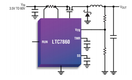
During normal operation, the switching surge stopper fully turns on the external MOSFET, allowing power to pass smoothly through the protection stage to power the subsequent load stage.
When an input voltage surge occurs, the operating mode is switched immediately, using the external MOSFET as part of a high-efficiency buck regulator to protect critical downstream components by limiting the output voltage and current.
In the protection state, the subsequent circuit will remain in working state.

Figure 5 Switching surge suppressor
Protecting the controller
The protection controller immediately disconnects when the power supply voltage is abnormal, thereby protecting the subsequent circuit.
In the protection state, the subsequent circuit will stop working.
Taking LTC4368 as an example, it can realize four protections: overvoltage (OV), undervoltage (UV), overcurrent (OC), and reverse input (RI), basically covering various working conditions that may occur in the application site, and providing a complete protection solution for the subsequent circuit.

Figure 6 LTC4368 block diagram
4. Product Examples
Alex shared ADI's linear surge suppressor LT4363.

Figure 7 LT4363 circuit architecture
LT4363 Introduction
It regulates the output voltage during overvoltage events (such as load dump conditions in automotive applications) by controlling the gate of an external N-channel MOSFET. The output is limited to a safe value, allowing the load to continue operating.
The LT4363 also monitors the voltage drop between the SNS and OUT pins to protect against overcurrent faults.
Regardless of the fault condition, the timer starts inversely proportional to the MOSFET stress. Before the timer expires, the FLT pin is pulled low to warn of an impending power failure. If the condition persists, the MOSFET turns off. The LT4363-1 remains off until reset, while the LT4363-2 restarts after a cool-down period.
Two high-precision comparators monitor the input supply for overvoltage (OV) and undervoltage (UV) conditions. When the voltage is below the UV threshold, the external MOSFET remains off. If the input supply voltage is above the OV threshold, the MOSFET is not allowed to turn back on. Back-to-back MOSFETs can be used in place of Schottky diodes for reverse input protection, reducing voltage drops and power losses. A shutdown pin reduces the quiescent current to less than 7μA during shutdown.
Design Points
Overvoltage fault
When an overvoltage condition occurs, LT4363 will control the MOSFET gate voltage to make the MOSFET work in the variable resistance area to ensure that the voltage on the output voltage sampling pin FB is maintained at 1.275V. This achieves the purpose of clamping the voltage at the voltage we set. At the same time, if the overvoltage phenomenon persists, the timer will control the MOSFET to turn off.
Overcurrent fault
When a short circuit or overcurrent condition occurs, the LT4363 controls the GATE pin to limit the current sense voltage between the SNS and OUT pins to 50 mV. In the case of a severe output short circuit (generally refers to an output voltage below 2V), the current sense threshold is reduced from the original 50 mV to 25mV to reduce the power stress on the MOSFET. If the fault persists, the timer controls the MOSFET to turn off.
MOSFET selection
The LT4363 conducts load current by driving an N-channel MOSFET. The important parameters of the MOSFET are the on-resistance RDS(ON), the maximum value of the drain-source voltage V(BR)DSS, the gate threshold voltage V(BR)GS, and SOA.
Maximum value of V(BR)DSS drain-source voltage:
The maximum value of the V(BR)DSS drain-source voltage must be higher than the highest supply voltage. If the output is shorted to ground or during an overvoltage event, the source and drain of the MOSFET will be subject to the full supply voltage.
V(BR)GS gate drive voltage:
For applications with VCC power supply above 9V, the general gate drive voltage range required is between 10V and 16V; for applications with VCC power supply below 9V, the gate drive voltage of N-channel MOSFET cannot be lower than 4.5V.
SOFTWARE OF MOSFET:
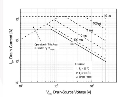
SOA (Safe Operation Area) is a parameter in all MOSFETs, which is reflected in the data sheet in the form of an icon. It reflects the relationship between three related parameters: Vds, Id, and time T. Take the N-MOSFET: FDB33N25 in a typical application as an example:

Figure 8 SOA curve of FET FDB33N25
When selecting the SOA of a MOSFET, it is important to consider what happens under all fault conditions;
In normal operation, the channel is fully open, so the power lost in the MOSFET is very small;
When an overvoltage or overcurrent fault occurs, the GATE pin will start to control the voltage across the DS on the MOSFET or the current flowing through the MOSFET. At this time, high voltage and high current will exist in the MOSFET at the same time, so the fault timer setting must be carefully determined according to the SOA data.
V. Conclusion
LT4363 is just one of ADI's many surge suppression controller series. In complex power supply environments such as automobiles and industries, the ADI surge suppressors provided by Shijian can help products withstand harsh power supply environments, enabling products to resist various surge damages and ensure reliable operation of products.
Previous article:TDK launches a series of ultra-small TVS for USB-C protection with lower capacitance
Next article:Polyimide Films for Digital Isolators
Recommended ReadingLatest update time:2024-11-16 11:30


- MathWorks and NXP Collaborate to Launch Model-Based Design Toolbox for Battery Management Systems
- STMicroelectronics' advanced galvanically isolated gate driver STGAP3S provides flexible protection for IGBTs and SiC MOSFETs
- New diaphragm-free solid-state lithium battery technology is launched: the distance between the positive and negative electrodes is less than 0.000001 meters
- [“Source” Observe the Autumn Series] Application and testing of the next generation of semiconductor gallium oxide device photodetectors
- 采用自主设计封装,绝缘电阻显著提高!ROHM开发出更高电压xEV系统的SiC肖特基势垒二极管
- Will GaN replace SiC? PI's disruptive 1700V InnoMux2 is here to demonstrate
- From Isolation to the Third and a Half Generation: Understanding Naxinwei's Gate Driver IC in One Article
- The appeal of 48 V technology: importance, benefits and key factors in system-level applications
- Important breakthrough in recycling of used lithium-ion batteries
- Innolux's intelligent steer-by-wire solution makes cars smarter and safer
- 8051 MCU - Parity Check
- How to efficiently balance the sensitivity of tactile sensing interfaces
- What should I do if the servo motor shakes? What causes the servo motor to shake quickly?
- 【Brushless Motor】Analysis of three-phase BLDC motor and sharing of two popular development boards
- Midea Industrial Technology's subsidiaries Clou Electronics and Hekang New Energy jointly appeared at the Munich Battery Energy Storage Exhibition and Solar Energy Exhibition
- Guoxin Sichen | Application of ferroelectric memory PB85RS2MC in power battery management, with a capacity of 2M
- Analysis of common faults of frequency converter
- In a head-on competition with Qualcomm, what kind of cockpit products has Intel come up with?
- Dalian Rongke's all-vanadium liquid flow battery energy storage equipment industrialization project has entered the sprint stage before production
- Allegro MicroSystems Introduces Advanced Magnetic and Inductive Position Sensing Solutions at Electronica 2024
- Car key in the left hand, liveness detection radar in the right hand, UWB is imperative for cars!
- After a decade of rapid development, domestic CIS has entered the market
- Aegis Dagger Battery + Thor EM-i Super Hybrid, Geely New Energy has thrown out two "king bombs"
- A brief discussion on functional safety - fault, error, and failure
- In the smart car 2.0 cycle, these core industry chains are facing major opportunities!
- The United States and Japan are developing new batteries. CATL faces challenges? How should China's new energy battery industry respond?
- Murata launches high-precision 6-axis inertial sensor for automobiles
- Ford patents pre-charge alarm to help save costs and respond to emergencies
- New real-time microcontroller system from Texas Instruments enables smarter processing in automotive and industrial applications
- How does this product function?
- 【Fudan Micro FM33LC046N Review】+ LED and KEY
- STM32F429IGT6 core board schematic diagram
- Ink display driver with 32KB SRAM cache
- Multiple uses of CC6678 digital signal processor (DSP)
- Debugger and programmer for RF SoCs
- MicroPython Hands-on (35) - Experience the Mini Game
- With simple wiring configuration, a single-stage stepper motor can be easily driven as a two-stage stepper motor
- Recommend a good book
- UBLOX M8N module one chip cannot be recognized


 New concept analog circuit 1-5
 \"New Concept Analog Circuit\" - Transistor [Text Version] (Yang Jianguo)


 京公网安备 11010802033920号