The system adopts the principle of ultrasonic distance measurement. Ultrasonic distance measuring instruments are generally composed of three parts: transmitter, receiver and signal processor. When working, the ultrasonic transmitter sends out ultrasonic pulses, and the ultrasonic receiver receives the reflected waves reflected by obstacles, accurately measuring the time from the ultrasonic wave being emitted to the reflected waves being reflected by obstacles. According to the propagation speed of ultrasonic waves, the distance of obstacles can be calculated. As a non-contact detection method, ultrasonic waves have the characteristics of small air propagation attenuation, strong reflection ability and penetration. Ultrasonic distance measurement has the advantages of being unaffected by light, rain, snow and fog within a short range, simple structure, convenient production and low cost. High-performance single-chip microcomputer combined with ultrasonic distance measurement can realize a powerful and easy-to-use reversing radar. TI's 16-bit single-chip microcomputer MSP430F2274 has extremely low power consumption and rich on-chip resources. At the same time, using JTAG interface technology, the on-chip flash memory can be easily programmed, which is convenient for software upgrades. It is very suitable as a microcontroller for reversing radar systems.

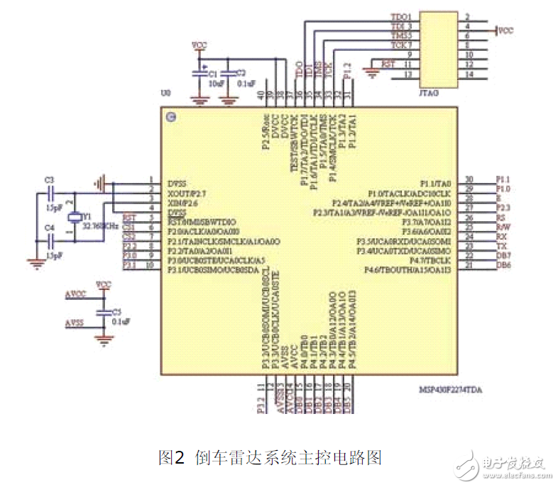
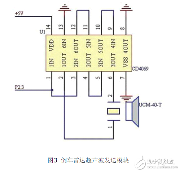
The main control circuit diagram of the system is shown in Figure 2. The MSP430F2274 chip selected in this system has 32Kb flash memory and 1Kb RAM, so there is no need to expand the memory externally. The external 32.768kHz crystal oscillator is used as the clock source of the Basic-Timer in the CPU shutdown state, and is also used as the on-board clock of the system. The ultrasonic transmission module circuit is shown in Figure 3, which consists of two parts: ultrasonic generation and emission. There are two methods for generating ultrasonic waves: hardware generation method and software generation method. The commonly used hardware generation method often adopts the following scheme: the ultrasonic wave is generated by the oscillator composed of CD4011, and is emitted by driving the ultrasonic transducer through the boost conversion. The start and stop of the oscillator are controlled by the single-chip microcomputer. This design adopts the software generation method, because the software generation method can not only reduce the complexity of the hardware and reduce the cost of the system, but also has the advantages of strong flexibility, easy implementation and good stability. This system uses the timer function of the MSP430F2274 microcontroller to generate a stable PWM (40Hz) pulse wave, and outputs it to the ultrasonic transmitter through the I/O port P2.3. In the ultrasonic transmitter circuit, CD4049 includes a total of 6 NOT gates, and only 3 are used in the circuit in Figure 3. In order to prevent interference or static breakdown that may damage the entire CD4049 , the 3 NOT gates on the unused side are connected in series for grounding. When the control end outputs a series of fixed-frequency pulses, the piezoelectric ceramic ultrasonic transmitter transducer UCM-40-T adds positive and reverse voltages at a fixed frequency to emit high-power ultrasonic waves, and the resulting waveform is more ideal than other methods.

The ultrasonic receiving circuit is shown in Figure 4. This is a difficult point in the design and debugging of this system. The piezoelectric ceramic ultrasonic receiver UCM-40-R receives the reflected ultrasonic wave and converts it into a 40kHz millivolt voltage signal, which needs to be amplified and processed before it can be used to trigger the interrupt of the single-chip microcomputer. On the one hand, the output signal of the sensor is weak. Due to different reflection conditions, the required amplification factor range is about 100 to 5000. On the other hand, the output impedance of the sensor is large, and a multi-stage amplifier circuit with high input impedance is required, and high input impedance is easy to receive interference signals. Two solutions are usually adopted: one is to use an operational amplifier to form a multi-stage frequency selection amplifier circuit; the other is to use a dedicated integrated preamplifier. The first solution is prone to self-oscillation. To make the receiving circuit achieve good sensitivity and anti-interference effect, the circuit debugging is more difficult. This system uses a dedicated integrated circuit preamplifier CX20106, which consists of a preamplifier, a limiting amplifier, a bandpass filter, a detector, an integrator, and a shaping circuit. The preamplifier has an automatic gain control function, which can ensure that the amplifier has a higher gain when the ultrasonic sensor receives a weak voltage from a distant reflected signal, and the amplifier will not be overloaded when the input signal is strong at a close distance. By adjusting the external resistor R3 of the chip pin 5 and setting the center frequency of its filter to 40kHz, a good effect is achieved. When a signal matching the center frequency of the filter is received, its output pin 7 outputs a low level, and the output pin 7 is directly connected to P2.2 of the MSP430F2274 to trigger an interrupt.


The alarm module uses a simple sound and light alarm circuit, as shown in Figure 5. First, a critical value is set. When the distance between the rear of the vehicle and the obstacle is less than the set minimum distance, the red indicator light flashes and the green indicator light goes out. The microcontroller sends a PWM pulse to its port. As the distance decreases, the duty cycle of the PWM pulse is controlled to increase the frequency of flashing and buzzing, thereby alerting the driver.

The communication interface circuit is shown in Figure 6. Using Maxim's MAX3232 chip, the peripheral circuit is very simple, requiring only five 0.1μF resistors. This circuit isolates the microcontroller serial port output signal and transforms it into an RS-232 signal and sends it to the car bus. It can also realize the communication of the system computer.

The keyboard and display circuit is shown in Figure 7, which consists of a keyboard and a liquid crystal display. The keyboard uses independent keys, with 3 keys, a setting key, an up key, and a down key. It can set various parameters such as alarm value, working mode, clock, etc. The liquid crystal display circuit uses ZJM12864BSBD, a low-power dot matrix LCD with a display format of 128 dots (columns) × 64 dots (rows). It has multi-function instructions and is easy to use. It can display clock, distance and alarm prompt information in real time, which is convenient and intuitive.
The program adopts a modular design and consists of multiple modules including the main program, distance measurement subroutine, keyboard display subroutine, clock display subroutine, etc. During the debugging process, each functional module and subroutine is debugged one by one. After each subroutine has completed its designated function, comprehensive debugging is performed.
Previous article:Interpretation of the circuit design of the visual fatigue elimination system
Next article:Op amp circuit bias current cancellation resistors, are they really needed?
- Popular Resources
- Popular amplifiers
- MathWorks and NXP Collaborate to Launch Model-Based Design Toolbox for Battery Management Systems
- STMicroelectronics' advanced galvanically isolated gate driver STGAP3S provides flexible protection for IGBTs and SiC MOSFETs
- New diaphragm-free solid-state lithium battery technology is launched: the distance between the positive and negative electrodes is less than 0.000001 meters
- [“Source” Observe the Autumn Series] Application and testing of the next generation of semiconductor gallium oxide device photodetectors
- 采用自主设计封装,绝缘电阻显著提高!ROHM开发出更高电压xEV系统的SiC肖特基势垒二极管
- Will GaN replace SiC? PI's disruptive 1700V InnoMux2 is here to demonstrate
- From Isolation to the Third and a Half Generation: Understanding Naxinwei's Gate Driver IC in One Article
- The appeal of 48 V technology: importance, benefits and key factors in system-level applications
- Important breakthrough in recycling of used lithium-ion batteries
- LED chemical incompatibility test to see which chemicals LEDs can be used with
- Application of ARM9 hardware coprocessor on WinCE embedded motherboard
- What are the key points for selecting rotor flowmeter?
- LM317 high power charger circuit
- A brief analysis of Embest's application and development of embedded medical devices
- Single-phase RC protection circuit
- stm32 PVD programmable voltage monitor
- Introduction and measurement of edge trigger and level trigger of 51 single chip microcomputer
- Improved design of Linux system software shell protection technology
- What to do if the ABB robot protection device stops
- Keysight Technologies Helps Samsung Electronics Successfully Validate FiRa® 2.0 Safe Distance Measurement Test Case
- Innovation is not limited to Meizhi, Welling will appear at the 2024 China Home Appliance Technology Conference
- Innovation is not limited to Meizhi, Welling will appear at the 2024 China Home Appliance Technology Conference
- Huawei's Strategic Department Director Gai Gang: The cumulative installed base of open source Euler operating system exceeds 10 million sets
- Download from the Internet--ARM Getting Started Notes
- Learn ARM development(22)
- Learn ARM development(21)
- Learn ARM development(20)
- Learn ARM development(19)
- Learn ARM development(14)
- How to change the library file in the schematic diagram in orcad?
- Free application: Domestic FPGA Gaoyunjia Little Bee Family GW1N Series Development Board
- Taking stock of the college entrance examination experience of Internet tycoons! How many points did you get in the exam?
- Without American EDA software, we can’t make chips?
- 【Share】Flash management tools: FAL (Flash Abstraction Layer) library
- [Awards awarded] Grab the post! Download the TWS headset white paper, write a wonderful review, and win a JD card!
- Constant voltage circuit and constant current circuit composed of operational amplifier and triode
- [RVB2601 Creative Application Development] Record the startup process of the hello world system
- How to initialize the key port of the power button in C language
- About the use and description of idconfig

 OPA336N/3K


 京公网安备 11010802033920号