Multichannel LED drivers are primarily designed to power multiple LEDs or multiple LED strings (sometimes with different colors or lengths) with a single IC. However, these drivers include a number of features that enable other compelling uses. For example, the LT3797 triple-channel LED driver can be configured to provide boost-then-buck capability, with one channel configured as a boost pre-regulator and the other two channels configured as buck-mode LED drivers.
When the input voltage source has a wide range of variations and can be above and below the rated voltage of the LED string, a buck-boost or SEPIC topology is often used. These topologies have some disadvantages compared to pure buck or pure boost regulators, namely: lower efficiency and bandwidth (reduced PWM dimming capability) compared to pure buck converters; and lower efficiency and higher conducted EMI compared to pure boost regulators.
One way to avoid this problem is to boost a wide range input with a voltage pre-regulator and use it as the input to a pure buck LED driver. The advantage of this approach is that it can implement both step-up and step-down with high PWM dimming bandwidth and low conducted EMI. Since the LT3797 has three channels that can be used for voltage regulation or LED driving, one channel can be used to boost the input voltage to a higher voltage that can then be used to power two high bandwidth buck mode LED drivers formed using the other two channels.

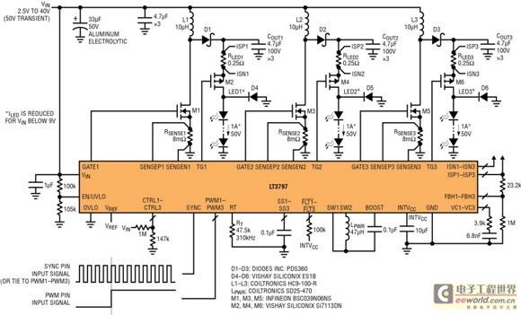
Figure 1: The LT3797 triple output LED driver configured as a 3 x 50V 1A boost LED driver
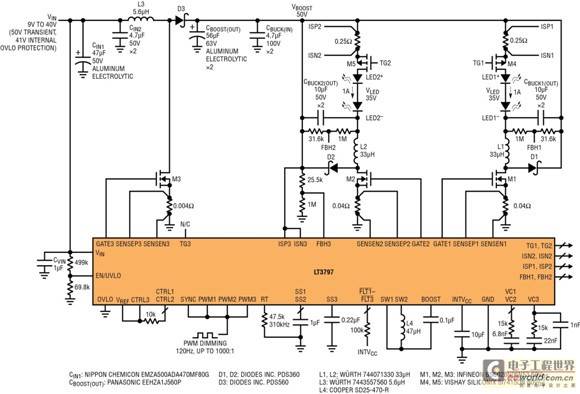
Using a buck LED driver can achieve higher PWM dimming ratios than using a boost mode driver. To achieve high LED dimming ratios with a wide range input, a pre-regulator can be used to boost the low input voltage to an intermediate voltage. This boosted intermediate output serves as the input to the buck mode LED driver. Figure 2 shows a boost-then-buck implementation using a single LT3797.

Figure 2: LT3797 dual-output step-up then step-down LED driver with 1000:1 PWM dimming ratio
Triple Output LED Driver (Multiple Topologies, High Efficiency)
The LT3797 is a triple output LED driver controller IC that can be used to provide current to three LED strings in a variety of topologies, including boost, buck, buck-boost, and SEPIC. Each channel operates independently of the other channels, but they share a common clock phase. LED current, open LED protection, analog, and PWM dimming control functions can be individually controlled.
The high-side feedback pin FBH provides universal overvoltage protection in both buck mode and buck-boost mode when the LED string is not connected back to GND, eliminating the need for a level-shift feedback transistor. The 2.5V to 40V VIN range and 100V output range give the LED driver high voltage and high supply capabilities. It can be used in automotive and industrial applications as well as battery-powered equipment.
Figure 1 shows a 93% efficient triple output boost LED driver that powers three 50W (50V, 1A) LED strings from an automotive input. The device features a 250:1 PWM dimming ratio at 120Hz and short-circuit protection. An internal buck-boost INTVCC supply delivers 7.8V gate charge voltage to the power switches, even when VIN drops as low as 2.5V, making it a very wide input range converter.

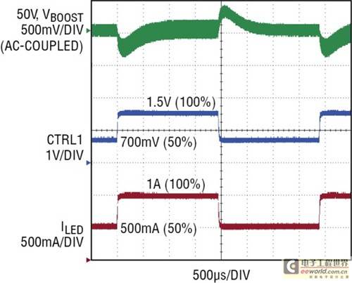
Figure 3: A simulated dimming transient from 50% (500mA) to 100% (1A) of full-scale current shows the high bandwidth of buck mode, even when the boost stage recovers at its own regular speed.
Dual Output Boost-then-Buck Mode LED Driver
The highest PWM dimming ratios can be achieved using buck LED drivers, which offer the highest operating bandwidth. To achieve high LED dimming ratios with a wide range of automotive input voltages, the automotive voltage must first be boosted using a pre-regulator. The boosted output voltage can then be used as the input to a buck mode LED driver. Figure 2 shows how this can be done with a single IC by using one channel of the LT3797 as a boost pre-regulator and the other two channels as buck mode LED drivers.
The advantage of this single-IC solution, in addition to reduced component count and cost compared to adding a separate boost IC as a pre-regulator, is that the PWM pin of the boost regulator can be used to disable switching and freeze the state of the control loop during the PWM off time. This allows the boost converter to quickly recover to its previous PWM on state, and its output will not sag when the buck mode LED driver turns back on. If the boost regulator's PWM is not turned off during the PWM off time, or a separate boost IC is used, the bandwidth of the boost converter will limit the maximum PWM dimming ratio.
An added benefit of a boost-then-buck mode driver is reduced conducted EMI compared to a similarly rated buck-boost regulator. Boost converters typically have lower conducted EMI around the AM band than buck converters due to the placement of the main inductor in series with the input. In a boost-then-buck scheme, the inductor is placed in series with the input, rather than a single buck-boost inductor between the buck and boost stages. While the basic buck-boost topology requires only a single inductor, a second input filter inductor is often required in high power LED driver applications to reduce conducted EMI.
The LT3797 dual output boost-then-buck LED driver shown in Figure 2 powers two 35W (35V, 1A) LED strings directly from an automotive input. It features a 1000:1 PWM dimming ratio at 120Hz. It also has short-circuit protection and LED open circuit protection. All three PWM dimming input pins are connected to the same PWM dimming input to maximize the PWM dimming ratio and freeze the control loop state of all three channels when PWM is off. The output of the boost channel is a regulated 50V. A higher boost output voltage will produce an even higher PWM dimming ratio, but at the expense of higher voltage rated power components and reduced efficiency. The two buck mode LED driver channels efficiently power two 1A, 35V LED strings from a 50V input. The overall converter efficiency is 87%.
High PWM dimming ratio
As mentioned above, buck and buck mode LED drivers offer higher bandwidth than boost topology drivers (including buck-boost and SEPIC converters), making it possible to achieve higher PWM dimming ratios. Unlike the boost topology, which continues to deliver more power to the output as the duty cycle increases, the output of the former briefly receives less power when the duty cycle increases to increase the inductor current during the transient. For this reason, the control loop of the buck converter can be optimized (separately from the boost converter) under higher bandwidth conditions.

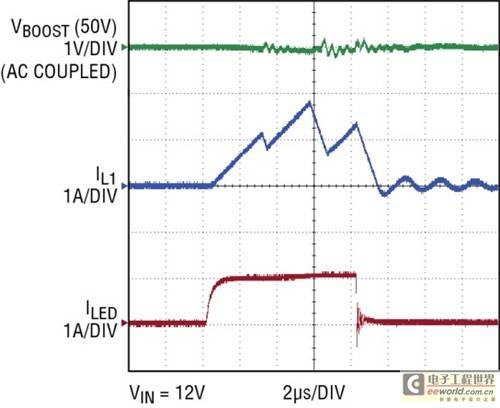
Figure 4: Dual-output boost-then-buck mode LED driver PWM dimming waveform. A dimming ratio of 1000:1 can be achieved at 120Hz frequency.
Additionally, during PWM dimming, the inductor current in the buck regulator does not have to ramp up as much at the beginning of each cycle as in the boost regulator, since its current is approximately equal to (rather than higher than) the LED current. This makes the buck converter superior to the boost converter in both transient response and PWM dimming ratio. As long as the boost pre-regulator does not lose its output charge voltage during transients, the boost-then-buck mode converter can mimic the high bandwidth of the buck converter.
Short and open LED protection
The LT3797 LED driver shown in Figures 1 and 2 is highly short-circuit resistant. The high-side PMOS disconnect is used not only for PWM dimming, but also for short-circuit protection (when one LED+ terminal is shorted to ground). Unique internal circuitry monitors for excessive output current conditions, shuts down the disconnect PMOS on that channel, and reports a fault. Likewise, if an LED string is removed or left open, the IC limits the maximum output voltage on that channel and reports a fault.
in conclusion
The LT3797 is a 2.5V to 40V input and up to 100V output triple-channel LED driver that can be used in a variety of topologies. When both step-up and step-down are required, one channel of the device can be used as a step-up pre-regulator while the other two channels are used as buck mode LED drivers for the highest PWM dimming ratios of 1000:1 or higher. Short-circuit protection is provided in all topologies, making the IC a rugged and powerful solution for driving LEDs in a wide range of applications.
Previous article:Digital test LCD control drive circuit test method
Next article:LED light strip installation and use precautions
Recommended ReadingLatest update time:2024-11-22 13:08


- Popular Resources
- Popular amplifiers
-
 西门子S7-12001500 PLC SCL语言编程从入门到精通 (北岛李工)
 -
 Small AC Servo Motor Control Circuit Design (by Masaru Ishijima; translated by Xue Liang and Zhu Jianjun, by Masaru Ishijima, Xue Liang, and Zhu Jianjun)
 -
 Intelligent Control Technology of Permanent Magnet Synchronous Motor (Written by Wang Jun)
 -
 100 Examples of Microcontroller C Language Applications (with CD-ROM, 3rd Edition) (Wang Huiliang, Wang Dongfeng, Dong Guanqiang)
- Vicor high-performance power modules enable the development of low-altitude avionics and EVTOL
- Bourns Launches Two Thick Film Resistor Series with High Power Dissipation Capabilities in Compact TO-220 and DPAK Package Designs
- Bourns Launches New High-Pulse Brake Resistor Series with Superior Energy Dissipation Capabilities
- Nexperia launches new 120 V/4 A half-bridge gate driver to further improve robustness and efficiency in industrial and automotive applications
- Vishay's New 150 V MOSFETs Offer Industry-Leading Power Loss Performance
- The first generation of SGT MOSFET series from Qiangmao: innovative trench technology, automotive-grade 60 VN channel, breakthrough in high-efficiency performance of automotive electronics
- DC/DC Power Supplies for Automotive Applications
- MathWorks and NXP Collaborate to Launch Model-Based Design Toolbox for Battery Management Systems
- STMicroelectronics' advanced galvanically isolated gate driver STGAP3S provides flexible protection for IGBTs and SiC MOSFETs
- Intel promotes AI with multi-dimensional efforts in technology, application, and ecology
- ChinaJoy Qualcomm Snapdragon Theme Pavilion takes you to experience the new changes in digital entertainment in the 5G era
- Infineon's latest generation IGBT technology platform enables precise control of speed and position
- Two test methods for LED lighting life
- Don't Let Lightning Induced Surges Scare You
- Application of brushless motor controller ML4425/4426
- Easy identification of LED power supply quality
- World's first integrated photovoltaic solar system completed in Israel
- Sliding window mean filter for avr microcontroller AD conversion
- What does call mean in the detailed explanation of ABB robot programming instructions?
- New IsoVu™ Isolated Current Probes: Bringing a New Dimension to Current Measurements
- New IsoVu™ Isolated Current Probes: Bringing a New Dimension to Current Measurements
- Infineon Technologies Launches ModusToolbox™ Motor Kit to Simplify Motor Control Development
- Infineon Technologies Launches ModusToolbox™ Motor Kit to Simplify Motor Control Development
- STMicroelectronics IO-Link Actuator Board Brings Turnkey Reference Design to Industrial Monitoring and Equipment Manufacturers
- Melexis uses coreless technology to reduce the size of current sensing devices
- Melexis uses coreless technology to reduce the size of current sensing devices
- Vicor high-performance power modules enable the development of low-altitude avionics and EVTOL
- Chuangshi Technology's first appearance at electronica 2024: accelerating the overseas expansion of domestic distributors
- Chuangshi Technology's first appearance at electronica 2024: accelerating the overseas expansion of domestic distributors
- The first time I drew a board, I couldn't burn the program into the JTAG after it was made. I cried
- How to generate a .txt file on CCS and burn it to MSP430
- Where can I find development information for the Samsung 4412 processor?
- TMS320C6678 memory access performance
- 4-digit LED digital display meter interfaced with PLC
- About Voltage Follower
- Advantages of combining TI analog devices with DSP
- SiC market is growing rapidly
- 【Chuanglong TL570x-EVM】Evaluation 07 - QT Date Interface Development
- Multi-market power management injects strong impetus into the growth of power MOSFET

 西门子S7-12001500 PLC SCL语言编程从入门到精通 (北岛李工)


 京公网安备 11010802033920号