1. Introduction
Road lighting is an important part of urban public facilities. At present, most of the domestic road lighting systems do not adopt network monitoring and management, and can only perform simple switch control of lighting equipment in units of regions. The switch control of most urban street lights is still decentralized by traditional transformers (distribution boxes), which cannot effectively monitor street lights and lack flexible and changeable operating systems. Therefore, there are a series of problems: such as complex systems and difficult unified management; wide coverage of street lights and difficult maintenance; low switch control efficiency and serious waste of electricity. In view of the current lack of control and management level of urban street lighting, the author designed a street light wireless monitoring system that can realize intelligent control of urban street lights and effectively save electricity. This system is mainly divided into three layers, namely, the street light management center with human-computer interaction interface function, the street light monitoring substation that gathers street light node information and sends street light control commands, and the street light control terminal that collects street light node information. The technical means of combining GPRS communication and ZigBee wireless communication are adopted to replace the traditional wired transmission. Among them, the communication between the street light management center and the street light monitoring substation adopts GPRS technology, which has the characteristics of wide coverage, high transmission rate, and can realize remote operation; the communication between the street light monitoring substation and the street light control terminal and between the street light control terminals adopts ZigBee technology.
2. System structure of street light monitoring network
This design adopts a solution combining GPRS technology and ZigBee technology, combining the advantages of both, saving costs and reducing the complexity of the system. The system adopts a three-layer model structure of "street light management center-street light monitoring substation-street light control terminal" to realize remote control operation of street lights. Among them, the communication between the street light management center and the street light monitoring substation adopts GPRS technology, and the communication between the street light monitoring substation and the street light control terminal and the street light control terminal adopts ZigBee technology. The object of the system operation is tens of thousands of street lights on urban roads. Through the management system, it is responsible for monitoring the various operating conditions of street lights, such as monitoring whether the voltage, current, power and other indicators of the current street light node meet the specifications, and can realize simple control of street light switches. The structure diagram of the entire street light monitoring system is shown in Figure 1.
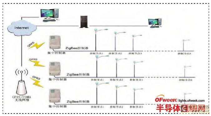
Figure 1 System structure diagram
ZigBee network topology can be divided into three categories: mesh structure, star structure and tree structure. After analyzing the topology of ZigBee network, considering that the street lamp monitoring covers a wide range and the natural environment is easily affected by weather, obstacles and electromagnetic radiation, it is inevitable that terminal nodes will fail. Therefore, star network and tree network are not suitable for use. Therefore, this system adopts mesh ZigBee network, which has a large communication range and can realize the function of route discovery. When the network fails, it can automatically repair and heal, thereby greatly improving the stability and reliability of the entire monitoring system, and using routing function transmission. The network structure is shown in Figure 2.
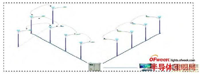
Figure 2: ZIGBEE network diagram
In a street light wireless monitoring system, there are multiple ZigBee networks, and the street lights in the vicinity of a street form a ZigBee network. Since street lights are evenly distributed on both sides of the road, and the distance between each two lights is generally 25~30m. Therefore, this system must first select a suitable location to place the ZigBee network coordinator. In the ZigBee network, the ZigBee network coordinator is responsible for establishing the network. Usually, the ZigBee network coordinator is used to realize the function of the street light monitoring substation and is responsible for maintaining the operating status of the street light nodes on the street. After the routing node joins the network, it plays the role of the control terminal in the street light monitoring system. In actual applications, in order to facilitate management, each street light control terminal can only join one ZigBee network to realize single light control. When all router nodes have successfully joined the network, the coordinator assigns network addresses to the routing nodes according to the mesh network topology.
3. System hardware design
3.1 ZigBee Coordinator Module Design
The ZigBee coordinator is mainly composed of a GPRS communication unit, a microprocessor, a communication unit and a power module. The coordinator is responsible for establishing a ZigBee network and realizing the sending and receiving of information. It needs to continuously collect various instructions sent by the monitoring center and send them to the control terminal, and at the same time feed back the terminal and line information to the monitoring center. The module structure diagram is shown in Figure 3. The processor uses an ARM7-based microprocessor module, transmits data through the serial port TTL level and the GPRS communication module, connects the communication module through the SPI serial port, and the power module converts 220V AC to 5V to power the processor, GPRS communication module and communication module. The communication module uses TI's ZigBee RF chip cc2530, and its main technical indicators include: the working frequency band is 2.4GHz; the number of channels is 16; the transmission power is 4.5dBm; and the receiving sensitivity is -97dBm.

Figure 3 ZigBee coordinator module
3.2 LED Street Light Control Module
In the street light control terminal, its hardware components mainly include MCU microcontroller unit, voltage and current information monitoring unit, RF module unit, LED street light drive control unit and power module. Its hardware structure is shown in Figure 4. As the CPU of the street light control terminal equipment, it is necessary to complete the communication with the RF module, the processing and storage of data packet transmission and reception, etc. In addition to requiring the MCU microcontroller to have sufficient storage space, it must also have strong data processing capabilities. This article uses the 32-bit series microcontroller with ARM Cortex-M3 core produced by STMicroelectronics, model STM32F103RBT6, which adopts LQFP (light and thin square flat) package structure, has 64 pins, and the appearance size is only 10mmX10mm. The price is between 10 yuan and 20 yuan. The power supply voltage is 2-3.6V, generally 3.3V power supply, with 2 12-bit analog-to-digital converters, and supports 7-channel DMA controller. The module pin diagram is shown in Figure 5.
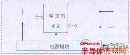
Figure 4 Hardware structure of LED street light control module
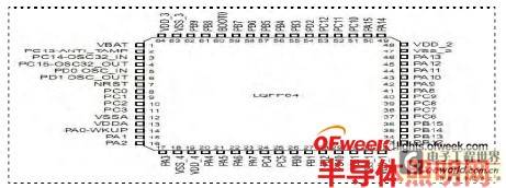
Figure 5 STM32F103RBT6 module pin diagram
In Figure 5, the MCU has three serial ports, namely UART1, UART2 and UART3, which are used to realize communication with other modules. Pins 42 and 43 are used as the sending and receiving pins of the DART 1 serial port, connected to the GPRS module, so as to realize the communication between the CPU and the GPRS module. This connection method is mainly for monitoring substation equipment, while the street light control terminal equipment is not connected to the GPRS module. Pins 16 and 17 are used as the sending and receiving pins of the UART2 serial port, connected to the RF module, so as to realize the communication between the CPU and the RF module. Pins 29 and 30 are used as the receiving and sending pins of the UART3 serial port, mainly to realize RS485 communication, connected to the LED control board, so as to realize the CPU driving the LED control board. Pin 14 of the MCU is used as the RS485 enable signal, connected to the 485 conversion chip, and according to the received 485 communication protocol, the LED drive control board is processed as a transceiver conversion device. Pin 15 of the MCU outputs a PWM signal to adjust the current size, so as to realize the brightness adjustment of the LED street light. Pins 21 and 22 of the MCU are connected to the security door interface of the detection unit to realize the anti-theft alarm function.
4. Software Design
4.1 Overall design of system software
This article uses MDK as the compilation environment for embedded system development, which supports the Cortex-M3 core processor of ARM7 architecture, automatically configures the startup code, integrates the Flash burning module, and has powerful simulation device simulation and performance analysis functions. The software layer of the wireless sensor network of this system is divided into three levels: hardware abstraction layer, system service layer and application layer.
Among them, the hardware abstraction layer transplanted the COS-Ⅱ embedded real-time operating system, shielded the hardware details for the upper layer, and provided drivers for hardware units such as power modules, MCU microprocessor modules and radio frequency communication modules. The system service layer mainly implements the task scheduling function of the operating system. By modifying the OS_CPU_A.S file, the CPU on/off interrupt and task switching are implemented in assembly language, and the transmission communication protocol is supported to complete the implementation of the routing algorithm. The application layer mainly implements the design function of the host computer software according to the user's definition.
According to the different transmission directions of data streams, this paper divides data transmission into reporting and sending. Reporting means that the street light control terminal sends data to the street light monitoring substation through the radio frequency module, and finally the street light monitoring substation transmits it to the street light management center through GPRS; the so-called sending means that the command issued by the street light management center is transmitted to the street light monitoring substation through GPRS, and then the street light monitoring substation sends it to the street light control terminal that needs to execute the operation command.
As shown in Figure 6, the main program flow chart of the system. Once the node is powered on, the initialization operation is first completed, mainly including the initialization configuration of the general I/O port, serial port, timer and radio frequency module of the MCU control module. Then the operating system is initialized. After the operating system is executed, the system enters an infinite loop state. During initialization, in order to reduce the power loss of the node, each node enters a dormant state. When an interrupt occurs, the task to be executed is triggered. At this time, the CPU will allocate resources for the task and execute the corresponding communication service subroutine. For example, the coordinator receives a command sent from the street light management center, which means that the coordinator has received an interrupt request. The node is started from the dormant state, executes the communication service subroutine, and receives the data packet sent from the management center. After receiving the data, the data must be verified. If the verification fails, the frame is discarded; otherwise, it is necessary to continue to determine whether it is a data packet sent to itself. If not, the coordinator needs to forward the data packet. Then the coordinator node will change from the receiving state to the sending state. After the transmission is successful, an interrupt request will be generated and it will enter the dormant state again, waiting for the next node state to be started.
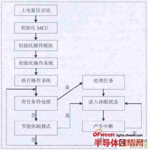
Figure 6 System main program flow chart
4.2 Street light monitoring substation processing information flow
The streetlight monitoring substation not only needs to establish a GPRS network with the streetlight management center, but also needs to establish a ZigBee network with the streetlight control terminal. The streetlight monitoring substation node is equipped with both a GPRS communication module and a radio frequency module. After the MCU of the device is initialized, the GPRS module is initialized through the serial port, and the GPRS network is connected according to the GPRS protocol, and then the main program loop task is entered. First, the ZigBee network communication channel is scanned. When the ZigBee network communication link is successful, data transmission is performed according to the network protocol. Figure 7 shows the main program flow chart of the streetlight monitoring substation.
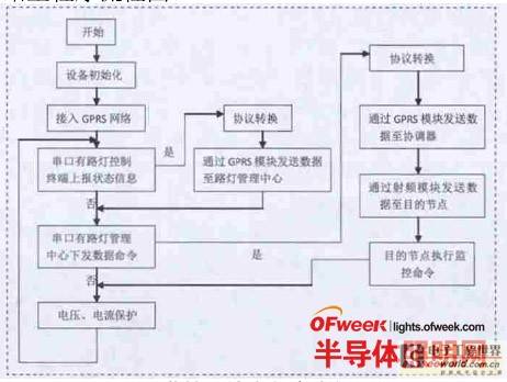
Figure 7 Monitoring substation main program flow chart
In Figure 7, after the monitoring substation is initialized, it enters the loop task of the system main program. The main function of the task loop is to monitor whether there is data reporting and sending on the MCU serial port. When the serial port UART 1 receives the monitoring command from the street light management center, the monitoring substation converts the protocol and routes it to the destination node through the RF module. The destination node executes the operation when receiving the monitoring command. When the serial port UART2 receives the node status information reported from the street light control terminal, the monitoring substation converts the protocol and sends the data to the street light management center through the GPRS network, sends the monitoring command, completes the on/off operation of the street light node, sets the brightness value, and sets the time for reporting voltage and current information. Reporting node status information can complete the overvoltage, overcurrent, undervoltage, undercurrent and anti-theft alarm operations of the street light node.
5. Main functions and components of the street light management center
The streetlight management center is responsible for supervising the operation status of streetlights, controlling the operation of streetlight nodes, and communicating with the streetlight monitoring substations on each street through GPRS. The monitoring substations are responsible for collecting and summarizing streetlight node information and transmitting it to the display interface of the streetlight management center. Through the display interface, control operations on each streetlight node can be performed and streetlight node operation status information can be obtained in a timely manner. If an alarm message appears, the geographical location of the fault will be immediately notified to the staff through the web page and sound prompts of the display interface so that timely response and processing can be made.
The main functions of the street light management center include:
(1) Realize individual control of each street light node
Users can turn on/off any street light on the main interface of the street light management center. The on/off status will be displayed on the corresponding street light node in the system interface, and the brightness value of the street light can be adjusted according to the PWM wave output by the MCU pin, which can achieve a brightness value change from 0-100%.
(2) Street light node status information display
If the foreground street light nodes are in operation, the node's voltage, current, power and other information will be displayed on the main interface, and the operating status information of any street light node in any time period can be queried, and a curve chart can be drawn based on this. According to the curve chart, a scientific assessment of the stability of the node operation can be made better.
(3) Fault and anti-theft alarm function
If at a certain moment, the sensor module detects fault alarms such as overvoltage, overcurrent, etc. at the front desk, and anti-theft alarms such as cable cutting and control panel theft, the main interface will immediately send an alarm message to the staff of the street light management center. After the alarm occurs, a new "map" interface will pop up on the main interface, showing the geographical location of the alarm node so that the staff can handle it conveniently.
6. Summary
Aiming at the shortcomings of the existing street light system in the city, this paper proposes a wireless street light monitoring system solution combining GPRS+ZigBee communication technology. This system realizes the digital information management of street lights, can remotely control the on/off of street lights, and monitor the status information of street lights in real time, reflecting modern control technology and intelligent management. Compared with the traditional street light control system, it can effectively eliminate the "all night lights" and "late night lights" phenomena, thereby greatly reducing energy costs and obtaining huge economic benefits. At the same time, through real-time monitoring and management of all street lights, it can greatly reduce the investment of manpower, material resources and financial resources in the later stage, and greatly improve work efficiency.
Previous article:What are the categories of lighting design?
Next article:Analysis of the full polarization design technology of LED tunnel light lens
Recommended ReadingLatest update time:2024-11-16 17:48


- Popular Resources
- Popular amplifiers
-
 Wireless Sensor Network Technology and Applications (Edited by Mou Si, Yin Hong, and Su Xing)
 -
 Detailed explanation and engineering practice of unmanned monitoring technology (Xie Jianbin, Li Peiqin, Yan Wei, Liu Tong, Lin Chenglong, Hong Quanyi, Zhou Hongfei, Cui Yibing)
 -
 Introduction to Wireless Sensor Networks (Edited by Ma Sasa et al.)
 -
 Introduction to the Internet of Things (Liu Yunhao)
- MathWorks and NXP Collaborate to Launch Model-Based Design Toolbox for Battery Management Systems
- STMicroelectronics' advanced galvanically isolated gate driver STGAP3S provides flexible protection for IGBTs and SiC MOSFETs
- New diaphragm-free solid-state lithium battery technology is launched: the distance between the positive and negative electrodes is less than 0.000001 meters
- [“Source” Observe the Autumn Series] Application and testing of the next generation of semiconductor gallium oxide device photodetectors
- 采用自主设计封装,绝缘电阻显著提高!ROHM开发出更高电压xEV系统的SiC肖特基势垒二极管
- Will GaN replace SiC? PI's disruptive 1700V InnoMux2 is here to demonstrate
- From Isolation to the Third and a Half Generation: Understanding Naxinwei's Gate Driver IC in One Article
- The appeal of 48 V technology: importance, benefits and key factors in system-level applications
- Important breakthrough in recycling of used lithium-ion batteries
- Innolux's intelligent steer-by-wire solution makes cars smarter and safer
- 8051 MCU - Parity Check
- How to efficiently balance the sensitivity of tactile sensing interfaces
- What should I do if the servo motor shakes? What causes the servo motor to shake quickly?
- 【Brushless Motor】Analysis of three-phase BLDC motor and sharing of two popular development boards
- Midea Industrial Technology's subsidiaries Clou Electronics and Hekang New Energy jointly appeared at the Munich Battery Energy Storage Exhibition and Solar Energy Exhibition
- Guoxin Sichen | Application of ferroelectric memory PB85RS2MC in power battery management, with a capacity of 2M
- Analysis of common faults of frequency converter
- In a head-on competition with Qualcomm, what kind of cockpit products has Intel come up with?
- Dalian Rongke's all-vanadium liquid flow battery energy storage equipment industrialization project has entered the sprint stage before production
- Allegro MicroSystems Introduces Advanced Magnetic and Inductive Position Sensing Solutions at Electronica 2024
- Car key in the left hand, liveness detection radar in the right hand, UWB is imperative for cars!
- After a decade of rapid development, domestic CIS has entered the market
- Aegis Dagger Battery + Thor EM-i Super Hybrid, Geely New Energy has thrown out two "king bombs"
- A brief discussion on functional safety - fault, error, and failure
- In the smart car 2.0 cycle, these core industry chains are facing major opportunities!
- The United States and Japan are developing new batteries. CATL faces challenges? How should China's new energy battery industry respond?
- Murata launches high-precision 6-axis inertial sensor for automobiles
- Ford patents pre-charge alarm to help save costs and respond to emergencies
- New real-time microcontroller system from Texas Instruments enables smarter processing in automotive and industrial applications
- Solving for the transfer characteristic curve of an op amp
- What does the typical transmission distance of an infrared receiver mean?
- GD32307E-START power on + led control
- Common options for compiling c6x
- [Silicon Labs BG22-EK4108A Bluetooth Development Evaluation] Evaluation 3: Try Keil/IAR Development
- Today at 10:00 AM Live: Comprehensive explanation of TI MSP Academy tutorial
- Overview of TI's 28335 chip
- 【STM32WB55 Review】+First Impressions
- The Relationship between DSP and FPGA in Embedded Development
- DSP Learning (4) Bus Structure

 Wireless Sensor Network Technology and Applications (Edited by Mou Si, Yin Hong, and Su Xing)
 Detailed explanation and engineering practice of unmanned monitoring technology (Xie Jianbin, Li Peiqin, Yan Wei, Liu Tong, Lin Chenglong, Hong Quanyi, Zhou Hongfei, Cui Yibing)


 京公网安备 11010802033920号