The arrangement of LEDs and the specifications of LED light sources determine the basic driver requirements. The main function of LED drivers is to limit the current flowing through LEDs under a certain range of operating conditions, regardless of how the input and output voltages change. The basic working circuit diagram of LED drivers is shown in Figure 1, where the so-called "isolation" means that there is no physical electrical connection between the AC line voltage and the LED (i.e., input and output). The most common method is to use a transformer for electrical isolation, while "non-isolation" does not use a high-frequency transformer for electrical isolation.
How to choose LED driving method
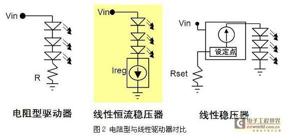
There are two types of typical LED drivers on the market today, namely linear drivers and switching drivers. The approximate application range is shown in Figure 2. For example, high-current applications with a current greater than 500mA use switching regulators, because linear drivers are limited by their own structure and cannot provide such a large current; in low-current applications with a current less than 200mA, linear regulators or separation regulators are usually used; and in medium-current applications between 200 and 500mA, both linear regulators and switching regulators can be used.
Switching regulators are energy efficient and provide excellent brightness control. Linear regulators are relatively simple in structure, easy to design, provide current regulation and overcurrent protection, and have no electromagnetic compatibility (EMC) issues.
In low-current LED applications, although resistor-type drivers are low-cost and simple in structure, they have low forward current under low voltage conditions, which can lead to insufficient LED brightness. In addition, the LED may be damaged under transient conditions such as load dump. In addition, resistors are energy-consuming components, so the energy efficiency of the entire solution is low, as shown in Figure 2.
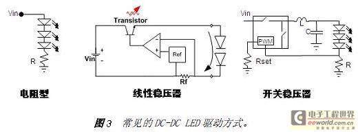
For example, in LED lighting applications using DC-DC power supplies, the LED drive methods that can be used include resistor type, linear regulator and switching regulator. The basic application diagram is shown in Figure 3.
In the resistive drive mode, the forward current of the LED can be controlled by adjusting the current detection resistor in series with the LED . This drive mode is easy to design, low cost, and has no electromagnetic compatibility (EMC) issues. The disadvantages are that it depends on voltage, requires binning of LEDs, and has low energy efficiency.
Linear regulators are also easy to design and have no EMC issues. They also support current stabilization and overcurrent protection (foldback), and provide external current set points. Their disadvantages are power dissipation, the input voltage must always be higher than the forward voltage, and low energy efficiency. Switching regulators use a PWM control module to continuously control the on and off of the switch (FET) to control the flow of current.
Switching regulators have higher energy efficiency, are independent of voltage, and can control brightness, but their disadvantages are relatively high cost, higher complexity, and electromagnetic interference (EMI) issues. Common topologies of LED DC-DC switching regulators include buck, boost, buck-boost, or single-ended primary inductor converter (SEPIC).
Among them, the buck structure is used when the lowest input voltage under all working conditions is greater than the maximum voltage of the LED string, such as using 24Vdc to drive 6 LEDs in series; on the contrary, the boost structure is used when the maximum input voltage under all working conditions is less than the lowest output voltage, such as using 12Vdc to drive 6 LEDs in series ; and when the input voltage and output voltage range overlap, the buck-boost or SEPIC structure can be used, such as using 12Vdc or 12Vac to drive 4 LEDs in series, but the cost and energy efficiency of this structure are the least ideal. Five Tips for LED Driver Design
1. Chip heating
This is mainly for high-voltage driver chips with built-in power modulators . If the chip consumes 2mA of current and a voltage of 300V is applied to the chip, the power consumption of the chip is 0.6W, which will of course cause the chip to heat up. The maximum current of the driver chip comes from the consumption of the driving power MOS tube. The simple calculation formula is I=cvf (considering the resistance effect of charging, the actual I=2cvf, where c is the cgs capacitance of the power MOS tube, and v is the gate voltage when the power tube is turned on. Therefore, in order to reduce the power consumption of the chip, you must find a way to reduce c, v and f. If c, v and f cannot be changed, then please find a way to distribute the power consumption of the chip to devices outside the chip, and be careful not to introduce additional power consumption. To put it simply, just consider better heat dissipation.
2. Power tube heating
The power consumption of the power tube is divided into two parts, switching loss and conduction loss. It should be noted that in most occasions, especially in LED mains drive applications, the switching loss is much greater than the conduction loss. The switching loss is related to the cgd and cgs of the power tube, as well as the driving ability and operating frequency of the chip. Therefore, the heating of the power tube can be solved from the following aspects:
A. You cannot select MOS power tubes based on the on-resistance alone, because the smaller the internal resistance, the larger the cgs and cgd capacitances. For example, the cgs of 1N60 is about 250pF, the cgs of 2N60 is about 350pF, and the cgs of 5N60 is about 1200pF. The difference is too big. When selecting a power tube, it is enough to use it.
B. The remaining is the frequency and chip driving capability, here we only talk about the impact of frequency. Frequency is also proportional to conduction loss, so when the power tube is hot, first think about whether the frequency is a bit high. Find a way to reduce the frequency! However, it should be noted that when the frequency is reduced, in order to obtain the same load capacity, the peak current must become larger or the inductance must also become larger, which may cause the inductor to enter the saturation region. If the inductor saturation current is large enough, you can consider changing CCM (continuous current mode) to DCM (discontinuous current mode), so you need to add a load capacitor.
3. Reduce the operating frequency
This is also a common phenomenon in the debugging process. Frequency reduction is mainly caused by two aspects: the ratio of input voltage to load voltage is small and the system interference is large. For the former, be careful not to set the load voltage too high, although the efficiency will be higher if the load voltage is high.
For the latter, you can try the following:
a. Set the minimum current to a smaller value;
b. Make the wiring clean, especially the key path of sense;
c. Select a smaller inductor or choose an inductor with a closed magnetic circuit;
d. Add RC low-pass filtering. This has a bad effect. The consistency of C is not good and the deviation is a bit large, but it should be enough for lighting. In any case, frequency reduction has no benefits, only disadvantages, so it must be solved.
4. Selection of inductor or transformer
Many users have reported that for the same drive circuit, there is no problem with the inductor produced by a, but the current of the inductor produced by b becomes smaller. In this case, you need to look at the inductor current waveform. Some engineers do not pay attention to this phenomenon and directly adjust the sense resistance or operating frequency to reach the required current. This may seriously affect the service life of the LED . Therefore, before designing, reasonable calculation is necessary. If the theoretical calculation parameters are a bit different from the debugging parameters, consider whether to reduce the frequency and whether the transformer is saturated. When the transformer is saturated, L will become smaller, causing the peak current increment caused by the transmission delay to rise sharply, and then the peak current of the LED will also increase. Under the premise that the average current remains unchanged, you can only watch the light decay.
5. LED current
We all know that if the LED ripple is too large, the LED life will be affected. Regarding the impact of excessive LED ripple, some LED manufacturers said that 30% is acceptable, but it was not verified later. It is recommended to control it as small as possible. If the heat dissipation is not well solved, the LED must be used at a reduced rating. I also hope that experts can give a specific indicator, otherwise it will affect the promotion of LED.
With regard to this article, I believe you will find that LED driver design is not difficult. You must have a clear idea in mind. As long as you calculate before debugging, measure during debugging, and age after debugging, I believe we can easily make LEDs .
Previous article:LED dimming system circuit design based on STC89C52 single chip microcomputer
Next article:A three-primary color LED driving principle and application IC circuit design scheme
- Popular Resources
- Popular amplifiers
- MathWorks and NXP Collaborate to Launch Model-Based Design Toolbox for Battery Management Systems
- STMicroelectronics' advanced galvanically isolated gate driver STGAP3S provides flexible protection for IGBTs and SiC MOSFETs
- New diaphragm-free solid-state lithium battery technology is launched: the distance between the positive and negative electrodes is less than 0.000001 meters
- [“Source” Observe the Autumn Series] Application and testing of the next generation of semiconductor gallium oxide device photodetectors
- 采用自主设计封装,绝缘电阻显著提高!ROHM开发出更高电压xEV系统的SiC肖特基势垒二极管
- Will GaN replace SiC? PI's disruptive 1700V InnoMux2 is here to demonstrate
- From Isolation to the Third and a Half Generation: Understanding Naxinwei's Gate Driver IC in One Article
- The appeal of 48 V technology: importance, benefits and key factors in system-level applications
- Important breakthrough in recycling of used lithium-ion batteries
- LED chemical incompatibility test to see which chemicals LEDs can be used with
- Application of ARM9 hardware coprocessor on WinCE embedded motherboard
- What are the key points for selecting rotor flowmeter?
- LM317 high power charger circuit
- A brief analysis of Embest's application and development of embedded medical devices
- Single-phase RC protection circuit
- stm32 PVD programmable voltage monitor
- Introduction and measurement of edge trigger and level trigger of 51 single chip microcomputer
- Improved design of Linux system software shell protection technology
- What to do if the ABB robot protection device stops
- Learn ARM development(19)
- Learn ARM development(14)
- Learn ARM development(15)
- Analysis of the application of several common contact parts in high-voltage connectors of new energy vehicles
- Wiring harness durability test and contact voltage drop test method
- From probes to power supplies, Tektronix is leading the way in comprehensive innovation in power electronics testing
- From probes to power supplies, Tektronix is leading the way in comprehensive innovation in power electronics testing
- Sn-doped CuO nanostructure-based ethanol gas sensor for real-time drunk driving detection in vehicles
- Design considerations for automotive battery wiring harness
- Do you know all the various motors commonly used in automotive electronics?
- Analysis of Embedded C Language Pointers
- How to read the radiator performance curve
- MSP430 interrupt vector table
- "Design Patterns in Talks" - Experience the great wisdom hidden in the evolution of design
- Ha ha ha ha
- ADUC7023 cannot connect to JTAG
- The timers in the MSP430G2553 chip, such as Timer_A, have a capture function. How to use it?
- Interrupt service routine jump of ARM embedded system
- Excellent GaN PA recommendation, please take a look if you are interested.
- [GD32E503 Review]——step01. Start the journey of experiencing the domestically produced M33


 5962-8687701GA


 京公网安备 11010802033920号