introduction
During the growth of crops, light conditions have an important impact on the growth rate, yield and quality of crops [1, 2]. At present, most of my country's facility agriculture still relies on incandescent lamps, halogen tungsten lamps, high-pressure mercury fluorescent lamps, high-pressure sodium lamps, etc. as light sources to supplement plant light [3-4]. These traditional supplementary lighting methods have disadvantages such as poor spectral matching [5-6], low light energy utilization, and failure to consider the impact of other environmental factors. Their high energy consumption makes it difficult to form a high input-output ratio in actual production. With the development of semiconductor technology, the use of LED cold light sources as supplementary light sources has also been proposed [7], which can solve the above-mentioned supplementary light source problems to a certain extent. However, since most research and development solutions and products still use a fixed light intensity and fixed light quality supplementary lighting method, without considering the differences in light requirements of different plants at different stages, the phenomenon of insufficient supplementary lighting and excessive supplementary lighting coexisting has not yet been truly solved. The problem of low-energy precision supplementary lighting [8].
In response to the above problems, this paper has developed an intelligent, accurate and energy-saving supplementary lighting system, which fully considers the influence of different plants in different stages and different environments on the amount of supplementary lighting required. Based on modern electronic information technologies such as sub-band light intensity detection technology and intelligent control technology, the STC12C5A60S2 single-chip microcomputer is used as the core processor [9] and the PT4115 is used as the LED driver module [10]. According to the temperature and light intensity detection results, the quantitative supplementary lighting of various plants in different wavelengths can be realized according to the demand in the appropriate environment. Under the premise of meeting the light required for their growth, the utilization rate of the output light energy is maximized, with the characteristics of low error, fast response speed, low cost and simple maintenance.
1 Overall system design
This system adopts modular design, which is divided into power module, detection module, control module, fill light module and user interaction module. The overall structure is shown in Figure 1. Among them, the power module is powered by solar energy, providing two power supply voltages of 5V and 12V respectively, to power the entire system; the intelligent control module uses the STC series microcontroller as the core, and according to the data collected by the system and the threshold value, it realizes the duty cycle calculation of the corresponding PWM control signal and the output of two PWM control signals; the detection module detects the red and blue light intensity and real-time temperature in different bands, and transmits the detection signal to the microcontroller after filtering and amplifying it, so as to realize the detection of relevant environmental information; the fill light module adopts two constant current drive circuits with PWM current control function to control the brightness of the red and blue LED fill light array lamps respectively, so as to realize quantitative and accurate fill light; the user interaction module uses an LCD screen to display the detection results, and the keyboard realizes the functions of threshold modification on demand, completes the threshold modification and setting, and effectively improves the convenience and scalability of the system.
2 Hardware Design
2.1 Power module
The power module of this system consists of a solar panel, a battery and a control circuit. The entire system is powered by solar cells. The schematic diagram is shown in Figure 2. Among them, the input end of the control circuit is connected to the solar cell, and the input voltage charges the 12V battery through the LM317 and its peripheral standard circuits. The battery powers the entire system. The output end of the battery uses the MIC29302 voltage regulator and transformer module to output a 12V regulated power supply signal, and adjusts the matching resistor to generate a 5V regulated power supply signal, thereby providing the 12V and 5V power supplies required by this system. Among them, the microcontroller, detection module and user interaction module are all powered by a 5V power supply, and the LED fill light module is powered by a 12V power supply.
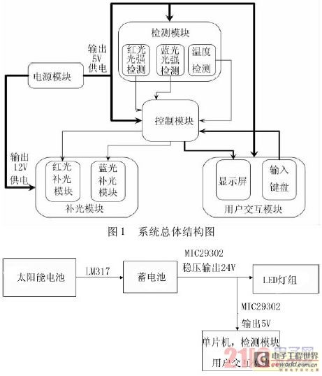
Figure 1. Schematic diagram of power module
2.2 Control module
The control module uses STC12C5A60S2 microcontroller as the core processor and is powered by 5V power supply. It has 8 10-bit A/D interfaces, 2 PWM output ports, 56K Flash storage space, 1 280B static access memory, and 1K programmable read-only memory. It completes node task scheduling, data acquisition, intelligent management, control signal output, threshold adjustment, data dump and other tasks. The circuit is shown in Figure 3. Among them, port P0 is connected to the 8-channel data port of the LCD screen; port P1 is responsible for connecting to the sampling signal, P1.0 is connected to the temperature detection signal, P1.1 is connected to the red light detection signal, and P1.2 is connected to the blue light detection signal, thereby completing the collection of sensor monitoring data; port P2 is connected to the 4 × 4 matrix keyboard, P3.0 and P3.1 are used for the data read and write lines connecting the microcontroller and the serial port to complete the program download; P3.2 to P3.7 are the LCD control terminals; P4.2 and P4.3 are the output ports of the microcontroller PWM control terminal, which calculate the PWM signal duty cycle corresponding to the required fill light amount of the two bands according to the microcontroller, and output PWM signals to control the brightness of the LED light group.
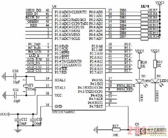
Figure: Control module circuit design
2.3 Detection module
The detection module uses light sensors and temperature sensors to detect the light intensity and temperature inside the facility in real time, and provides the collected data to the single-chip microcomputer for processing. The schematic diagram is shown in Figure 4. Among them, the temperature detection module is composed of the temperature sensor 18B20 and its standard conditioning circuit. The data line is connected to the P1.0 port of the single-chip microcomputer to realize the temperature collection. Light detection includes red light intensity detection and blue light intensity detection. The blue light 2BU6 silicon photocell with a wavelength range of 400 to 500nm and the red light 2BU6 silicon photocell with a wavelength range of 600 to 700nm are used as detection elements. The 4-way operational amplifier LM324 is used to design the operational amplifier to convert and amplify the weak analog signal of the silicon photocell respectively, and finally the analog signal is connected to the P1.1 and P1.2 ports of the single-chip microcomputer for A/D conversion, thereby realizing the sub-band light intensity detection.
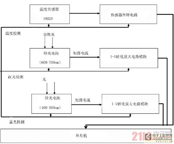
Figure 1. Schematic diagram of the detection module
2.4 Fill light module
The fill light module includes an LED light group and its driving circuit. The driving circuit adopts the PT4115 driving module circuit. The red light and blue light modules work independently. The schematic diagram is shown in Figure 5. Among them, the LED light group adopts a narrow-band red light LED array with a rated power of 1W and a central wavelength of 660nm and a narrow-band blue light LED array with a central wavelength of 450nm. The two PWM signals output by the single-chip microcomputer are connected to the DIM control terminals of the red and blue light PT4115 respectively. The red light driver chip is connected to the PWM signal generated by P4.2, and the blue light is connected to the PWM signal generated by P4.3. The output current of the driver chip PT4115 is controlled by the PWM signal, thereby realizing the quantitative fill light of the LED light group.
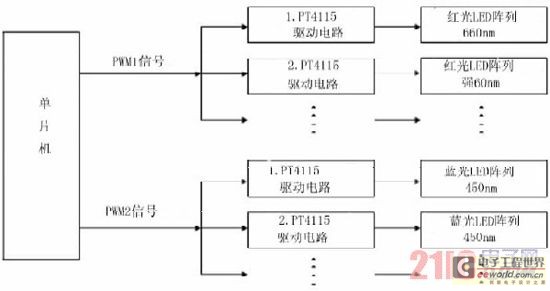
Figure 1. Schematic diagram of fill light module
2.5 User Interaction Module
The user interaction module mainly consists of two parts: LCD screen and keyboard. The LCD screen adopts OCM12864-3 LCD screen, which can realize the query and display of system data; and the keyboard adopts 4 × 4 matrix keyboard to realize the setting and change of system related data.
3 Software Design
The system software mainly includes sensor analysis function, data management and parameter setting program, PWM signal control program and display program, realizing 3 types of parameter settings, environmental factor collection and automatic control functions of the controlled light group. The software flow is shown in Figure 6. When the system is working, the temperature and red and blue light intensity thresholds need to be set first. The temperature sensor periodically monitors the temperature in the facility to determine whether the temperature exceeds the threshold range that is not conducive to photosynthesis. If it exceeds, the LED fill light group is turned off. When the temperature is within the set threshold range, the red and blue light intensity are detected respectively. When the actual light intensity is within the threshold, the system enters the automatic quantitative fill light state, and the actual light requirement is calculated according to the difference between the set threshold and the actual value. Then, according to the duty cycle of the two PWM control signals corresponding to the actual light requirement, the corresponding PWM signals are generated respectively, so as to achieve the purpose of controlling the brightness of the LED lamp and implementing accurate fill light for plants.
4. Operation Results Analysis
The system fully considers various factors affecting plant light supplementation. Through monitoring, setting, data management and decision-making procedures of various factors, it accurately calculates the overall difference between the light required by the plant and the actual light, and uses the mean method to calculate the output light intensity of each LED; based on the relationship between LED drive current and output light intensity, the system can control the amount of light supplementation by controlling the PWM output current. The system was put into trial use at the melon base of Northwest Agriculture and Forestry University in 2010, realizing various partial functions in the design scheme, and can effectively achieve quantitative and accurate light supplementation for a long time. Figure 7 is the prototype interface of the device.
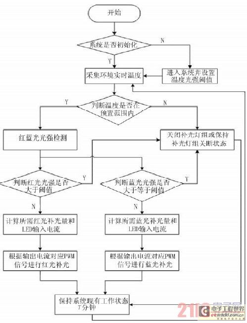
Figure, software flow chart
5 Conclusion
This paper develops a plant intelligent and precise lighting system based on the STC12C5A60S2 single-chip microcomputer. The system uses solar power to control the driving current of the two-way red and blue LED light groups of specific wavelengths through the core processor STC12C5A60S2 using PWM signals according to the monitoring results of the temperature and light sensors, thereby controlling the brightness of the light source, solving the shortcomings of existing lighting equipment, and realizing intelligent and precise lighting for crops. System tests have proved that it has good stability and can meet the requirements of intelligent and precise lighting for different plants at different growth stages. The yield and quality of crop products are improved, and energy consumption is significantly reduced. At the same time, it has the characteristics of low error, fast response speed, easy use, flexible deployment, low cost, and simple maintenance.
Previous article:Basic knowledge of LED dimming
Next article:4.2 W GU10 LED Lighting Driver Using Primary-Side Feedback
Recommended ReadingLatest update time:2024-11-16 15:47


- Popular Resources
- Popular amplifiers
- MathWorks and NXP Collaborate to Launch Model-Based Design Toolbox for Battery Management Systems
- STMicroelectronics' advanced galvanically isolated gate driver STGAP3S provides flexible protection for IGBTs and SiC MOSFETs
- New diaphragm-free solid-state lithium battery technology is launched: the distance between the positive and negative electrodes is less than 0.000001 meters
- [“Source” Observe the Autumn Series] Application and testing of the next generation of semiconductor gallium oxide device photodetectors
- 采用自主设计封装,绝缘电阻显著提高!ROHM开发出更高电压xEV系统的SiC肖特基势垒二极管
- Will GaN replace SiC? PI's disruptive 1700V InnoMux2 is here to demonstrate
- From Isolation to the Third and a Half Generation: Understanding Naxinwei's Gate Driver IC in One Article
- The appeal of 48 V technology: importance, benefits and key factors in system-level applications
- Important breakthrough in recycling of used lithium-ion batteries
- Innolux's intelligent steer-by-wire solution makes cars smarter and safer
- 8051 MCU - Parity Check
- How to efficiently balance the sensitivity of tactile sensing interfaces
- What should I do if the servo motor shakes? What causes the servo motor to shake quickly?
- 【Brushless Motor】Analysis of three-phase BLDC motor and sharing of two popular development boards
- Midea Industrial Technology's subsidiaries Clou Electronics and Hekang New Energy jointly appeared at the Munich Battery Energy Storage Exhibition and Solar Energy Exhibition
- Guoxin Sichen | Application of ferroelectric memory PB85RS2MC in power battery management, with a capacity of 2M
- Analysis of common faults of frequency converter
- In a head-on competition with Qualcomm, what kind of cockpit products has Intel come up with?
- Dalian Rongke's all-vanadium liquid flow battery energy storage equipment industrialization project has entered the sprint stage before production
- Allegro MicroSystems Introduces Advanced Magnetic and Inductive Position Sensing Solutions at Electronica 2024
- Car key in the left hand, liveness detection radar in the right hand, UWB is imperative for cars!
- After a decade of rapid development, domestic CIS has entered the market
- Aegis Dagger Battery + Thor EM-i Super Hybrid, Geely New Energy has thrown out two "king bombs"
- A brief discussion on functional safety - fault, error, and failure
- In the smart car 2.0 cycle, these core industry chains are facing major opportunities!
- The United States and Japan are developing new batteries. CATL faces challenges? How should China's new energy battery industry respond?
- Murata launches high-precision 6-axis inertial sensor for automobiles
- Ford patents pre-charge alarm to help save costs and respond to emergencies
- New real-time microcontroller system from Texas Instruments enables smarter processing in automotive and industrial applications
- 555 classic circuit diagram: DC-AC converter diagram composed of 555 circuit
- Is there any mobile phone positioning software that you would recommend?
- TI Live: A detailed discussion of a candidate solution for "electric vehicle on-board charger". Will it be popular among engineers?
- DSPC6678 on-chip storage space allocation mechanism
- EEWORLD University Hall ---- Computer Control Devices Zhang Guangxin of Zhejiang University
- The most worrying thing happened: ARM complies with new US regulations and stops cooperating with Huawei
- Summary of remote firmware upgrade for MSP430, STM8L, cortex-M0 core
- Do all voltage rails need to use low quiescent current? Here's the answer!
- How Carrier Networks Will Achieve 5G 《Vintage Multi-Carrier Technology》
- Mentor Use

 Siemens PLC Project Tutorial
 LED Cube Code
 ESP32-S3 source code


 京公网安备 11010802033920号