|
OLED stands for Organic Light-Emitting Diode, which is an organic light-emitting diode display. It refers to a technology in which organic semiconductor materials and luminescent materials are driven by current to emit light and realize display. OLED has many advantages over LCD: ultra-light, ultra-thin (thickness can be less than 1 mm), high brightness, large viewing angle (up to 170°), emitting light from the pixels themselves without the need for a backlight, low power consumption, It has fast response speed (about 1,000 times the speed of LCD), high definition, low heat generation, excellent shock resistance, low manufacturing cost, and bendability. Therefore, OLED is more capable of displaying perfect videos and consumes less power. It can be used as a display screen for mobile phones, digital TVs and other products. It is recognized by the industry as the next generation display technology with the most development prospects. 1 Characteristics of P13501 display module 2 Controller and structural block diagram of the display module
| ||
The structural block diagram of the module is shown in Figure 1.
The interface of SSD1303 includes data input buffer, data output latch, instruction register and decoder, busy state flip-flop and timing control circuit, etc. It has a high-performance interface control circuit. The computer can access the SSD1303 at any time without determining its current status. Since OLED uses Intel 8080 timing, both BS1 and BS2 are connected to high level; and since there is no command/data selection line in AT91RM9200, one line PB10 in its general port PB is used as the command/data selection line of OLED. When PB1O is low level, it means that the data written to OLED is a command word; when it is high level, it means that the data written to OLED is a data word. The 16-pin RES of OLED is the reset pin and can be directly connected to the reset circuit of ARM. However, in order to facilitate the reset control of OLED, another port line PB11 is specially used for reset control. The OLED chip select signal USER1_CS is generated by decoding the NCS4 of the AT91RM9200 and the address lines A25, A23, and A22 through a 38-bit decoder. After calculation, its physical address is 0x52800000. The interface circuit design between OLED and AT91RM9200 is shown in Figure 2.
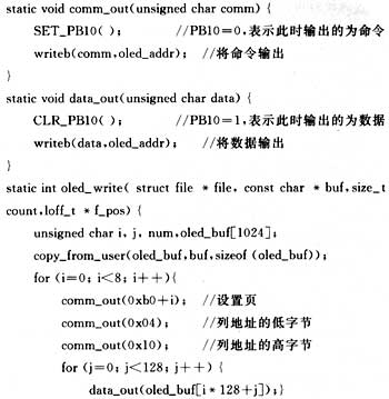
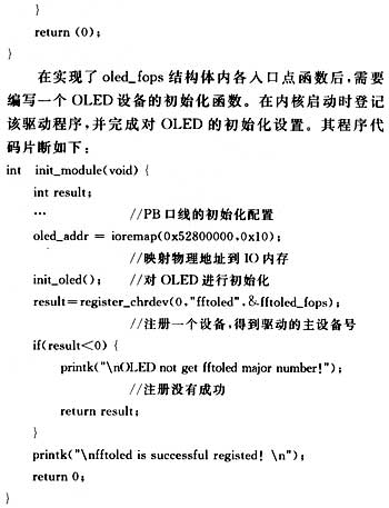
operating system is to shield the users from the particularities of the hardware, making the application irrelevant to the underlying specific physical device. Device drivers are the bridge between applications and specific hardware. Linux supports three types of hardware devices: character devices, block devices and network devices. They are written in roughly the same way. Among them, character devices and block devices can be accessed like files. The main difference between character devices and block devices is that every I/O operation of an application on a character device will be directly passed to the corresponding driver of the system kernel; while an application's operations on a block device must go through the system's buffer management. , passed indirectly to the driver for processing. Here, OLED is a character device. Usually, character devices provide a process control interface to applications, mainly including open, close (or release), read, write, ioctl, poll, mmap, etc. Adding a character device driver to the system actually means adding corresponding code to the above operations. For character devices and block devices, the Linux kernel provides a unified abstraction of these operations and defines them in the structure file_operations. For most character devices, only a few of these operations are required for the driver to work just fine. As needed, the OLED device driver only implements some device operations and declares its file_operations structure in a tokenized format, as follows:  oled_write is responsible for displaying the data to be displayed on the OLED screen; oled_ioctl is used to implement various control commands for OLED; oled_open is responsible for opening the OLED display; oled_release is responsible for closing the OLED display. Here we mainly introduce the specific implementation of oled_write. Others can be implemented according to actual needs with reference to oled_write. The specific program to implement oled_write is as follows:   5 Driver Compilation After the driver is written, it needs to be compiled. In the Linux operating system, there are generally two compilation methods for drivers, namely static compilation and dynamic compilation. During static compilation, the driver is directly compiled into the kernel and can be freely tailored when configuring the kernel. Assume that the written driver of P13501 is myoled. c, the specific operations to statically compile it into the kernel are as follows: ①Invert myoled. c Copy to the drivers/char directory, and modify drivers/char/Config. in file. Add the following code there: dep_tristate my oled support' CONFIG_MY_OLED /usr/local/arm/2.95.3/bin/arm-linux-gcc-O2-DMODULE-D__KERNEL__-I/home/sum/linux-2.4.19/include-c myoled. c It is assumed here that the cross-compiler path is: /usr/local/. The storage path of the kernel is: /home/sum/linux-2.4.19. If there are no errors during compilation, myoled will be generated after completion. ofile. Copy it to a directory in the embedded system (for example: /home), and you can load it dynamically: Repeated loading and unloading can complete the debugging of the OLED driver. 6 Conclusion |
Previous article:Interface and display design of liquid crystal controller SED1520 and microcontroller mPSD3334D
Next article:LED lamp life cycle assessment shows that LED lamps have excellent environmental performance
Recommended ReadingLatest update time:2024-11-16 23:39


- Popular Resources
- Popular amplifiers
-
 Siemens Motion Control Technology and Engineering Applications (Tongxue, edited by Wu Xiaojun)
 -
 Modern Product Design Guide
 -
 Modern arc welding power supply and its control
 -
 Small AC Servo Motor Control Circuit Design (by Masaru Ishijima; translated by Xue Liang and Zhu Jianjun, by Masaru Ishijima, Xue Liang, and Zhu Jianjun)
- MathWorks and NXP Collaborate to Launch Model-Based Design Toolbox for Battery Management Systems
- STMicroelectronics' advanced galvanically isolated gate driver STGAP3S provides flexible protection for IGBTs and SiC MOSFETs
- New diaphragm-free solid-state lithium battery technology is launched: the distance between the positive and negative electrodes is less than 0.000001 meters
- [“Source” Observe the Autumn Series] Application and testing of the next generation of semiconductor gallium oxide device photodetectors
- 采用自主设计封装,绝缘电阻显著提高!ROHM开发出更高电压xEV系统的SiC肖特基势垒二极管
- Will GaN replace SiC? PI's disruptive 1700V InnoMux2 is here to demonstrate
- From Isolation to the Third and a Half Generation: Understanding Naxinwei's Gate Driver IC in One Article
- The appeal of 48 V technology: importance, benefits and key factors in system-level applications
- Important breakthrough in recycling of used lithium-ion batteries
- Innolux's intelligent steer-by-wire solution makes cars smarter and safer
- 8051 MCU - Parity Check
- How to efficiently balance the sensitivity of tactile sensing interfaces
- What should I do if the servo motor shakes? What causes the servo motor to shake quickly?
- 【Brushless Motor】Analysis of three-phase BLDC motor and sharing of two popular development boards
- Midea Industrial Technology's subsidiaries Clou Electronics and Hekang New Energy jointly appeared at the Munich Battery Energy Storage Exhibition and Solar Energy Exhibition
- Guoxin Sichen | Application of ferroelectric memory PB85RS2MC in power battery management, with a capacity of 2M
- Analysis of common faults of frequency converter
- In a head-on competition with Qualcomm, what kind of cockpit products has Intel come up with?
- Dalian Rongke's all-vanadium liquid flow battery energy storage equipment industrialization project has entered the sprint stage before production
- Allegro MicroSystems Introduces Advanced Magnetic and Inductive Position Sensing Solutions at Electronica 2024
- Car key in the left hand, liveness detection radar in the right hand, UWB is imperative for cars!
- After a decade of rapid development, domestic CIS has entered the market
- Aegis Dagger Battery + Thor EM-i Super Hybrid, Geely New Energy has thrown out two "king bombs"
- A brief discussion on functional safety - fault, error, and failure
- In the smart car 2.0 cycle, these core industry chains are facing major opportunities!
- The United States and Japan are developing new batteries. CATL faces challenges? How should China's new energy battery industry respond?
- Murata launches high-precision 6-axis inertial sensor for automobiles
- Ford patents pre-charge alarm to help save costs and respond to emergencies
- New real-time microcontroller system from Texas Instruments enables smarter processing in automotive and industrial applications
- EEWORLD University Hall ---- Learn FPGA with you ---- Hao Xushuai team of Sanxin Intelligent
- How to distinguish between field effect transistors and Schottky diodes?
- Introduction to the internal structure of C2000
- Award-winning review: Qinheng RISC-V architecture 32-bit general-purpose MCU CH32V103
- Keep moving forward + review my 2018
- 【IoT Development】Zhengdian Atom STM32 Battleship v3+Gizwits AIoT+APP Control
- Let me express my feelings and talk about phone calls and scammers
- Some knowledge points about low-frequency amplifiers
- MC33063A boost circuit, burning IC and electrolytic capacitor? With pictures, help!
- Could anyone help me see what is wrong with my amplifier circuit?


 Siemens Motion Control Technology and Engineering Applications (Tongxue, edited by Wu Xiaojun)


 京公网安备 11010802033920号