In the algorithm based on linear fitting, the more traditional algorithm predicts the position at time k+2 based on the measured values at time k and k+1, which is easy to cause inaccurate prediction and target node loss. However, energy factors are crucial for sensor networks, so we should find ways to improve the tracking and positioning accuracy under the premise of low computational complexity. Based on the idea of linear fitting, this paper analyzes the characteristics of the tracking process, selects appropriate prediction data and adopts a multi-cluster head structure to improve tracking accuracy and reduce the target loss rate.
2 Related Work
2.1 Prediction data selection
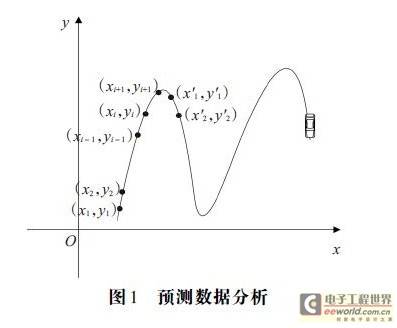
Although there is no regularity in the target's motion trajectory, its motion trend remains unchanged for a considerable period of time. As shown in Figure 1, this is the situation when the target moves forward along the X axis on a two-dimensional plane (the trajectory in the figure is an arbitrary curve, and for the convenience of description, when the target turns, it is called reaching the extreme point). It can be seen that when the target is between two extreme points, the increase and decrease along the X axis and Y axis remain unchanged; when reaching the extreme point, the increase and decrease along the X axis or Y axis will change. Since the target's motion trend remains unchanged between the two extreme points, the historical data during this period can be used to predict the trajectory, that is, to use a section of data with the same trend to predict the next position of the target node, and the extreme point is used as the dividing line.

Use the sign function to determine whether the extreme point has been reached. As shown in Figure 1, when the target moves along the positive direction of the X axis, if Sgn (xi-xi-1) * Sgn (yi-yi-1) == Sgn (xi+1-xi) * Sgn (yi+1-yi), it means that the target has not reached the extreme point, otherwise it means that the target has reached the extreme point; when the target moves in the opposite direction, the increase and decrease of the X axis and the Y axis change simultaneously.
Set F is used to store historical data required for prediction. Before reaching the first extreme point, (x1, y1). (x2, y2)… (xi, yi) can be used to predict the position of (xi+1, yi+1). At this time, set F={(xr, yr)|r=1,2,…, i}. Use the symbol function to determine whether the target has reached the extreme point. If it has reached the extreme point, that is, Sgn(xi-xi-1)*Sgn(yi-yi-1)/Sgn(xi+1-xi)*Sgn(yi+1-yi), then clear all data items in set F, put the current positioning coordinates and the previous positioning coordinates in F to form a new data information set; otherwise, continue to add new data items to set F.
2.2 Multi-level cluster head structure
Cluster heads of different levels are used to complete different tasks at different stages, ultimately achieving the goal of improving positioning and tracking accuracy and reducing the target loss rate. Cluster heads are divided into: main cluster head, auxiliary cluster head and reserve cluster head.
The selection of the main cluster head needs to take into account the residual energy and the distance from the target node. The node with larger energy and closer distance to the target should be selected as the main cluster head. Assume that the residual energy of the current cluster head i is Ei, and the measured distance from the target is Di. The threshold Ti of cluster head i is calculated according to formula (1):

Where ci represents the trend factor, and its initial value is 1. The trend factor indicates which cluster head node the target will tend to move towards in the future. If it tends to cluster head node i, the reserve cluster head nodes around cluster head node i will monitor the target node information earlier. The trend factor is determined by the number of reserve cluster heads received by the auxiliary cluster head.
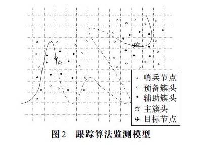
Initially, the main cluster head is the sentinel node that discovers the target; when the target is lost, the recovery mechanism is used to track the target and re-establish the tracking mechanism. At this time, the main cluster head is the cluster head node that discovers the target. Except for the above two cases, the main cluster head compares the thresholds of the current auxiliary cluster heads and selects the node with a larger threshold as the main cluster head of the next stage. After the main cluster head is selected, its adjacent cluster head node serves as the auxiliary cluster head, and the adjacent cluster head node of the auxiliary cluster head serves as the reserve cluster head to establish a tracking mechanism, as shown in Figure 2.

The three cluster heads complete different tasks. The main cluster head mainly completes the fusion of node information in the cluster and performs weighted fusion of the auxiliary cluster head information to form the final positioning position; the auxiliary cluster head receives the information sent by the nodes in the cluster for initial positioning and sends the positioning result to the main cluster head; the reserve cluster head is prepared to monitor the target on the one hand and prevent the target from being lost on the other hand, and its nodes in the cluster are in a dormant state. When the reserve cluster head senses the target information, it informs the auxiliary cluster head. The auxiliary cluster head regards the reserve cluster head as a node in the cluster, integrates the information from the reserve cluster head, and records the number of reserve cluster heads as the value of the trend factor when electing the main cluster head.
3 Target Tracking Algorithm
3.1 Target Monitoring Model
The entire monitoring area is divided into many virtual cells using a grid structure. The sensor nodes in each cell form a cluster. When the energy of the cluster head node is less than a certain threshold, the cluster head is replaced, and each node has two states: monitoring and sleeping.
Energy saving is an important evaluation index in the study of wireless sensor networks. Many scholars study tracking algorithms based on energy factors. In order to save the energy of sensor nodes, most nodes should be in a dormant state when no target appears, and only a small number of nodes are needed to monitor whether the target appears. This paper sets a sentinel node (acted by the cluster head node at the border) at the border of the monitoring area to detect whether a target enters the monitoring area. The border cluster head periodically generates a number between 0 and N randomly. If the number is greater than N/2 (N is the total number of border nodes), the cluster head node is a sentinel node. In order to prevent the sentinel node from running out of energy, cluster head election is required. The relationship between the remaining energy of the sentinel node and a certain threshold is compared to decide whether to elect a cluster head. The sentinel node is in a listening state, and the non-border cluster head node and the nodes in the cluster are in a dormant state. When the target appears, the sentinel node wakes up its neighboring cluster head node as an auxiliary cluster head, and the auxiliary cluster head node wakes up its non-primary and auxiliary cluster head nodes as reserve cluster heads to establish a monitoring mechanism.
During the communication process, the sensor nodes only need to communicate with adjacent nodes. Assuming that the side length of the grid is r, the communication radius is 2r; the auxiliary cluster head node and the main cluster head node need to locate the target, so the sensor perception radius is 2r. The cluster head election adopts the strategy of literature 11, and each sensor node has simple computing capabilities. The tracking algorithm monitoring model is shown in Figure 2.
3.2 Target Detection and Positioning
After the sentinel node finds the target, it immediately wakes up the neighboring cluster head node, and the neighboring cluster head node successively wakes up the nodes in the cluster for monitoring. Initially, the sentinel node establishes a tracking mechanism as the main cluster head node, and then the main cluster head. The auxiliary cluster head cooperates with the nodes in its cluster to start monitoring the signals emitted by the target and positioning.
Sensor nodes can determine the distance between each other through the transmitted signals. The algorithms that can measure distance include TOA (Time Of Arrival) algorithm, TDOA (Time Difference Of Arrival) algorithm, AOA (Angle Of Arrival) algorithm and RSSI (Received Signal Strength) algorithm. Since the sensor node itself will send out RSSI signals and the distance value can be obtained independently according to the strength of the signal, this paper adopts the RSSI algorithm, in which the sensing node calculates the distance dij between the target and the measured received signal carrier power as follows:

Where d0=1 m, P0=-30 dBm, α=3.
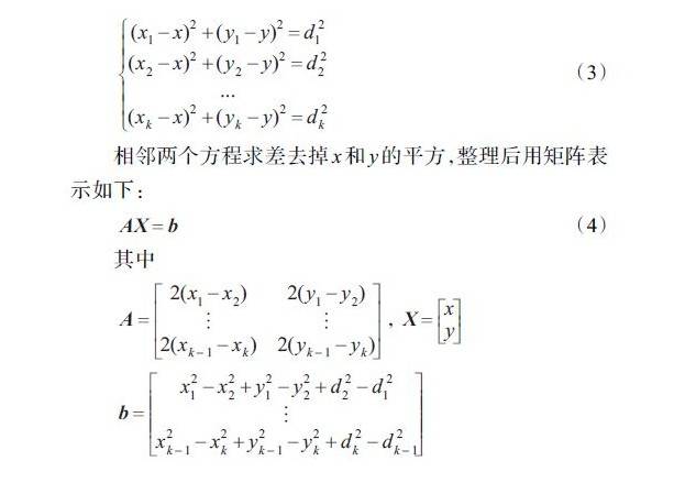
After receiving the target signal, the nodes in the cluster send the information to the cluster head node, which uses multilateral measurement to calculate the coordinates of the target. Assume that at time t, there are k sensor nodes in the cluster head node i, whose coordinates are (x1, y1), (x2, y2), ..., (xk, yk), and the distances to the target node (x, y) are d1, d2, ..., dk, respectively. According to the polygon positioning model, we have:

Due to the presence of ranging error, a random error vector ξ is added (ξ is n-1 dimension), and AX + ξ = b is obtained. The least squares algorithm is used to obtain the value of X when ξ is minimum. Let Q(X) = ξ2 = AX – b2, and take the derivative of X to obtain the estimated position of the target:

The coordinates of the target node are preliminarily calculated through formula (5), and then the auxiliary cluster head sends the positioning information to the main cluster head node. The main cluster head fuses the information from n-1 auxiliary cluster heads and calculates the average through formula (6) to obtain the final target location.

The three types of cluster heads transform into each other in the whole network. The main cluster head judges the difference between two adjacent signals received. If the signal difference is less than zero, it means that the target is far away from the main cluster head node. At this time, the main cluster head node sends a message to re-elect the main cluster head. The auxiliary cluster head that receives this message calculates its own threshold Ti and sends it to the main cluster head node. The main cluster head node selects the node with the largest threshold as the next main cluster head node, retreats to the auxiliary cluster head node, and updates the tracking mechanism. When the auxiliary cluster head node and its cluster nodes cannot receive the target signal, the cluster nodes of the auxiliary cluster head sleep and become the reserve cluster head. If the reserve cluster head receives the target signal and the tracking mechanism updates one of its neighboring nodes to become the main cluster head node, the reserve cluster head is converted into an auxiliary cluster head and wakes up the nodes in the cluster for positioning. However, when the reserve cluster head finds that its neighboring cluster head node is a reserve cluster head or a common cluster head, it stops working and becomes a common cluster head node.
Previous article:A TDMA Scheme Based on Real-time Information in Wireless Sensor Networks
Next article:Application of Home Internet of Things Technology in Smart Home System
- Popular Resources
- Popular amplifiers
- Mir T527 series core board, high-performance vehicle video surveillance, departmental standard all-in-one solution
- Akamai Expands Control Over Media Platforms with New Video Workflow Capabilities
- Tsinghua Unigroup launches the world's first open architecture security chip E450R, which has obtained the National Security Level 2 Certification
- Pickering exhibits a variety of modular signal switches and simulation solutions at the Defense Electronics Show
- Parker Hannifin Launches Service Master COMPACT Measuring Device for Field Monitoring and Diagnostics
- Connection and distance: A new trend in security cameras - Wi-Fi HaLow brings longer transmission distance and lower power consumption
- Smartway made a strong appearance at the 2023 CPSE Expo with a number of blockbuster products
- Dual-wheel drive, Intellifusion launches 12TOPS edge vision SoC
- Toyota receives Japanese administrative guidance due to information leakage case involving 2.41 million pieces of user data
- LED chemical incompatibility test to see which chemicals LEDs can be used with
- Application of ARM9 hardware coprocessor on WinCE embedded motherboard
- What are the key points for selecting rotor flowmeter?
- LM317 high power charger circuit
- A brief analysis of Embest's application and development of embedded medical devices
- Single-phase RC protection circuit
- stm32 PVD programmable voltage monitor
- Introduction and measurement of edge trigger and level trigger of 51 single chip microcomputer
- Improved design of Linux system software shell protection technology
- What to do if the ABB robot protection device stops
- Detailed explanation of intelligent car body perception system
- How to solve the problem that the servo drive is not enabled
- Why does the servo drive not power on?
- What point should I connect to when the servo is turned on?
- How to turn on the internal enable of Panasonic servo drive?
- What is the rigidity setting of Panasonic servo drive?
- How to change the inertia ratio of Panasonic servo drive
- What is the inertia ratio of the servo motor?
- Is it better for the motor to have a large or small moment of inertia?
- What is the difference between low inertia and high inertia of servo motors?
- MSP430 MCU Development Record (16)
- I posted a thread about icebabycool. He didn't answer the question but laughed at me instead of showing my low IQ. Please punish this kind of rogue behavior severely.
- Help with POE design issues
- [Voice and vision module based on ESP32S3] Material unpacking—ESP32S3 BOX
- PCBA intelligent detection fixture, one-click generation of test reports
- How to choose the right inductor in a switching power supply
- EEWORLD University Hall----Introduction to Isolated Modulator
- A brief introduction to the use of the console for learning common components of RT-Thread
- How to derive the w/w0 result in the low-pass response in the fourth edition of Circuit Design Based on Operational Amplifiers and Analog Integrated Circuits...
- Connecting a stepper motor using the MSP430G2 LaunchPad

 SPT206AIH


 京公网安备 11010802033920号