An oscilloscope is an essential tool for measuring power ripple and power noise. However, in actual measurements, how to choose the appropriate bandwidth, sampling rate, probe, oscilloscope coupling method, and even grounding will have different effects on the measurement results. The following summarizes some key considerations from specific practical cases. (This article is compiled from the Power Technology Seminar hosted by 21ic)
Definition of Power Ripple and Power Noise
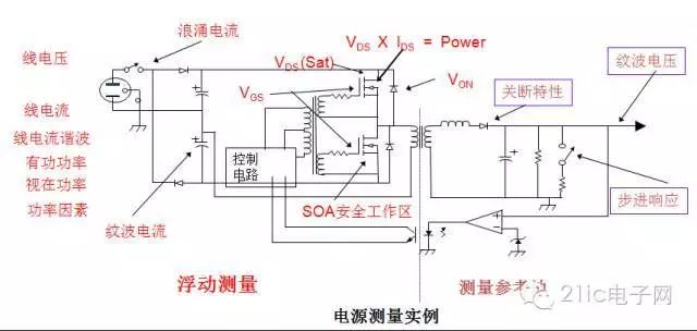
At present, there is no standard definition given by an association for power ripple and power noise. However, the industry has gradually formed a common saying that power ripple is understood as the fluctuation of the output voltage of the power module including VRM, which has nothing to do with the complex power supply network, or the fluctuation of the voltage at the source end (Source end) of the power supply output. Power noise refers to the voltage fluctuation at the chip pin when the power module works in the actual product system and transmits the power energy to the chip pin through the power distribution network, or simply the voltage fluctuation at the end (Sink end) of the power output.
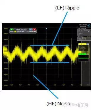
It can also be said that the voltage fluctuation at the source is called ripple (Ripple), and at the end is called noise (Noise).

Among the many test items of switching power supplies, power ripple and power noise are important test items.

Power supply ripple and noise displayed on an oscilloscope.
1. Oscilloscope bandwidth selection
Bandwidth is the most important indicator of an oscilloscope. Theoretically, as long as the bandwidth covers 99.9% of the energy of the measured signal, the measurement error can be less than 3%, which is the appropriate bandwidth. Therefore, there are also multiple bandwidth selection rules in the industry, such as: 5 times rule, three times the sine wave frequency, 1.8 times rule, 1/3 rule. Different rules are applied to different measurement signals and measurement requirements.
Based on the relationship between rise time and bandwidth, it seems that we can conclude that the higher the bandwidth, the smaller the measurement error.
But in fact, this is not the case in specific applications. After all, the oscilloscope is not an ideal instrument, and the measurement system itself has noise. These noises include amplifier noise, ADC noise, active probe noise, spatial radiation noise induced by the probe ground wire, and conducted noise coupled by the ground loop. From the perspective of signal-to-noise ratio, the bandwidth is appropriate only when the energy of the measured signal is much greater than the noise energy brought by the oscilloscope measurement system itself, that is, when the signal-to-noise ratio is large enough.
The bandwidth selection for power supply ripple measurement depends on the rise time of the power switch tube. The bandwidth for measuring ripple is equal to the bandwidth for measuring the switch tube. Generally, the switching frequency of a low-power power supply can reach 1MHz or even greater, and the corresponding rise time of the switch tube is smaller. The switching frequency of a high-power power switch tube is small, only 100KHz or even smaller, and the rise time is large. However, the rise time of most switch tubes MOSFET is up to 100ns. Even if the rise time of the switch tube is only 30ns, 1/3 of the rise time is 10ns, and the rise time of a 100MHz oscilloscope is only 3.5ns. Therefore, it is sufficient to use a 100MHz bandwidth oscilloscope to measure the switch tube of the switching power supply. In fact, there are very few switch tubes with a rise time of only 30ns, so limiting the bandwidth to 20MHz is sufficient. This is also the reason why many people say that "the bandwidth of the oscilloscope needs to be limited to 20MHz when measuring power supply ripple."
Of course, some switches require higher bandwidths. For example, the new CoolMOS has a rise time of 11ns and a fall time of 3ns, and a bandwidth of at least 300MHz.
2. Selection of sampling rate when measuring power supply ripple
In general, you can select the sampling rate according to the sampling rate required for measuring the switch tube. For most MOS tubes, 250MS/s is sufficient. Remember: the principle of selecting the sampling rate is to sample 3-5 points on the rising edge of the waveform details of interest, preferably more than 5 points. Of course, a high sampling rate reduces the distortion of the test waveform.

3. Capture time required to measure power supply ripple
The power ripple based on the 220V AC input of the power grid includes switching frequency and power frequency components; the power frequency component is the 100Hz signal after rectification. It takes 20ms to capture two complete 100Hz cycles, so it is recommended to set the time base to more than 2ms/div.
Please remember: Memory depth = sampling rate * sampling time
When the storage depth is constant, the faster the storage speed, the shorter the storage time, and there is an inverse relationship between them.
Increasing the storage depth of an oscilloscope can indirectly increase the sampling rate of the oscilloscope: when measuring waveforms over a longer period of time, since the storage depth is fixed, the sampling rate can only be reduced to achieve this, but this will inevitably result in a decrease in waveform quality; if the storage depth is increased, it can be measured at a higher sampling rate to obtain an undistorted waveform.
4. The lower the noise floor of the oscilloscope required for measurement, the better
The background noise refers to the baseline amplitude when there is no signal input to the oscilloscope. Users can only see the thickness of the baseline with their naked eyes, or measure the Pk-Pk, SDEV or RMS value of the baseline.
As a standard test equipment, if the oscilloscope itself has a large background noise, it will be difficult to measure the true situation of the measured signal.
If the noise floor of the measurement system composed of an oscilloscope and a probe is close to or greater than the power supply ripple/power supply noise being measured, that is, the measured signal-to-noise ratio (SNR) is too small, the power supply ripple/power supply noise is submerged by the local noise of the oscilloscope.
5. Oscilloscope detection method
●The problem of using a 10:1 probe attenuation circuit to amplify the background noise by 10 times
The input impedance of the oscilloscope and the impedance of the probe form an attenuator circuit. The oscilloscope will automatically detect the probe's attenuation ratio and readjust the oscilloscope's vertical range setting to reflect the probe's attenuation. Using a 10:1 probe means that the oscilloscope's current vertical range setting is 10 times the oscilloscope's internal amplifier input. The signal is attenuated, but the noise is not. The software amplifies the attenuated signal by 10 times, and the noise is also amplified by 10 times.
Therefore, the choice of detection method will have different impacts on the test results. Whether to choose a 10:1 passive probe, a 1:1 passive probe, or a 1:1 coaxial cable needs to be determined based on your actual situation.
●1:1 coaxial cable is necessary for weak power supply ripple/noise measurement
Using a probe with too large an attenuation factor will also make it impossible to set the oscilloscope's vertical sensitivity to the minimum, which will lead to greater quantization errors. If a conventional passive probe or active probe is used, the minimum gear can only be 10mV/div or 20mv/div due to the attenuation factor of 10:1. At the 20mV gear, the background noise is usually greater than 30mV, and voltages such as 1.8/2.5 cannot be accurately tested. At the 20mV gear, the probe's offset voltage can be adjusted in a very small range. If DC coupling is used, some voltages may not be measured.
6. Oscilloscope Coupling Method
●AC 1M ohm or DC 50 ohm + DC blocking capacitor?
The power supply and ground impedance at the chip end are usually in the milliohm level. After the high-frequency power supply noise is transmitted from the coaxial cable to the oscilloscope channel, when the oscilloscope input impedance is 50 ohms, the characteristic impedance of the coaxial cable of 50 ohms is completely matched with the channel, and there is no reflection; when the channel input impedance is 1M ohms, it is equivalent to high impedance. According to the transmission line theory, the power supply noise is reflected, thus causing the power supply noise tested at 1M ohm input impedance to be higher than 50 ohms.

●Load effect
When the probe is connected to a circuit, it draws energy from the circuit and sends it to the oscilloscope. The probe is a "circuit network" and an additional "load" that the signal source must drive.
The left side of the red line in the right figure represents the circuit to be tested. When the probe on the right side of the red line is connected, the probe absorbs current from the signal source. The circuit network of this probe includes resistance, inductance and capacitance.
If the impedance of the probe is much larger than the impedance of the circuit being measured (usually 50 ohms for high-speed circuits), the current absorbed by the probe will be very, very small. If the impedance of the probe is equal to the circuit impedance, the current absorbed from the circuit being measured is the same as the current flowing through the circuit being measured.
If the probe absorbs too much current from the circuit under test, the circuit under test will malfunction or even stop functioning normally. Usually, the circuit under test still appears to be working normally, but due to the current being absorbed, the measured signal voltage drops, which will affect the user's judgment of the true situation of the circuit under test if the probe's loading effect is not well understood.
●Is the oscilloscope set to DC coupling or AC coupling?
The only reason to set AC coupling is that in DC coupling, some oscilloscopes do not have enough offset voltage range when the range is only 2mv/div or even smaller.
Previous article:Oscilloscope Probe FAQs
Next article:How to use an oscilloscope to measure the most accurate power ripple
- New IsoVu™ Isolated Current Probes: Bringing a New Dimension to Current Measurements
- Modern manufacturing strategies drive continuous improvement in ICT online testing
- Methods for Correlation of Contact and Non-Contact Measurements
- Keysight Technologies Helps Samsung Electronics Successfully Validate FiRa® 2.0 Safe Distance Measurement Test Case
- From probes to power supplies, Tektronix is leading the way in comprehensive innovation in power electronics testing
- Seizing the Opportunities in the Chinese Application Market: NI's Challenges and Answers
- Tektronix Launches Breakthrough Power Measurement Tools to Accelerate Innovation as Global Electrification Accelerates
- Not all oscilloscopes are created equal: Why ADCs and low noise floor matter
- Enable TekHSI high-speed interface function to accelerate the remote transmission of waveform data
- Intel promotes AI with multi-dimensional efforts in technology, application, and ecology
- ChinaJoy Qualcomm Snapdragon Theme Pavilion takes you to experience the new changes in digital entertainment in the 5G era
- Infineon's latest generation IGBT technology platform enables precise control of speed and position
- Two test methods for LED lighting life
- Don't Let Lightning Induced Surges Scare You
- Application of brushless motor controller ML4425/4426
- Easy identification of LED power supply quality
- World's first integrated photovoltaic solar system completed in Israel
- Sliding window mean filter for avr microcontroller AD conversion
- What does call mean in the detailed explanation of ABB robot programming instructions?
- STMicroelectronics discloses its 2027-2028 financial model and path to achieve its 2030 goals
- 2024 China Automotive Charging and Battery Swapping Ecosystem Conference held in Taiyuan
- State-owned enterprises team up to invest in solid-state battery giant
- The evolution of electronic and electrical architecture is accelerating
- The first! National Automotive Chip Quality Inspection Center established
- BYD releases self-developed automotive chip using 4nm process, with a running score of up to 1.15 million
- GEODNET launches GEO-PULSE, a car GPS navigation device
- Should Chinese car companies develop their own high-computing chips?
- Infineon and Siemens combine embedded automotive software platform with microcontrollers to provide the necessary functions for next-generation SDVs
- Continental launches invisible biometric sensor display to monitor passengers' vital signs
- LPC11U68 driver X-NUCLEO-IKS01A3
- Live: Unveiling the secrets of the new generation of C2000 microcontrollers for servo and motor drive applications
- Analysis and layout of differential signal lines in practical applications
- BQ40Z50-R2 security mode introduction and password modification method
- Reduce the "buzz" in your cell phone with a fully differential audio power amplifier
- MSP430i2041 freezes
- msp430f1232 minimum system and debugging process
- Technical guidance: What is the difference between lead-spray tin and lead-free tin spray on the pads on the PCB?
- Smart warehouse based on Gizwits AIoT development platform
- [RT-Thread Reading Notes] Part 2 (5) Interrupt Management and Bidirectional Linked List


 Multisim Circuit System Design and Simulation Tutorial
 Application of static fields


 京公网安备 11010802033920号