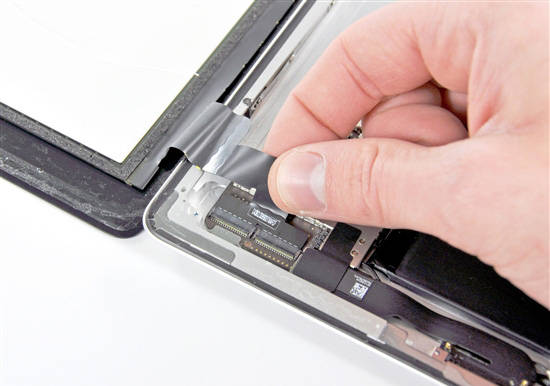
An engineer in Shenzhen Futian Huaqiangbei who specializes in screen development and production needs to use an oscilloscope to measure a series of pulse signals when the Apple tablet computer iPad powers on the screen. After the oscilloscope captures the pulse signal, he can simulate the signal. However, this friend failed to measure it several times, or was not satisfied with the captured signal, so he brought his Macoshine tablet oscilloscope and other related equipment to consult.

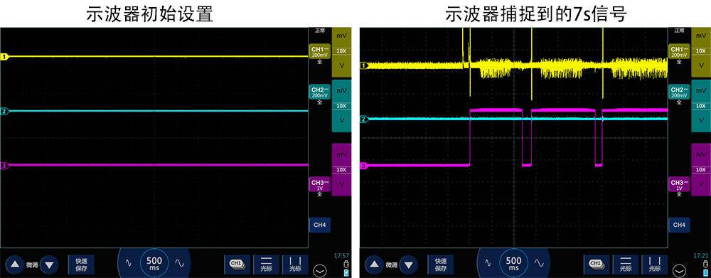
First, he demonstrated his measurement method. He needed to measure three signals in total, connected to three channels of the oscilloscope. When channel three was powered on to generate a direct current, channel one and channel two would each generate a pulse with a positive and negative interval and different pulse widths. What he needed to observe was the pulse change pattern of channel one, and use it as a basis for simulation.
The DC generated by channel 3 is around 2.5V, and the pulses of channel 1 and channel 2 are within ±500mV. Therefore, he set the vertical range of channel 1 and channel 2 to 200mV/div, and the vertical range of channel 3 to 1V/div. Then he set the time base of the oscilloscope to 500ms, which means that one screen records a waveform of 500*14ms, that is, a signal of 7 seconds in length.

Then he connected the signal to three channels respectively, and powered on the oscilloscope. The oscilloscope entered the scrolling mode at the 500ms time base, so he could see the signal changes in real time. After capturing a screen of signals, he pressed the pause button, then adjusted the time base to expand the signal and observed the signal at the pulse-intensive part of channel 1. However, the waveform he saw after expansion disappointed him greatly, because the expected square wave turned into a sawtooth wave. Some pulse signals were even lost.

Actually, there is nothing wrong with his operation. The problem is that his operation requires the oscilloscope to have a large storage depth, so that when the time base is increased, the sampling rate will not be reduced too much. The cycle of his pulse signal is actually around 1us, that is, the frequency of 1M. At this time, the bandwidth of the oscilloscope still meets the measurement conditions, but the sampling rate has been reduced too much due to the limitation of the storage depth. The ideal measurement sampling rate should be around 5M/s-20M/s.
Here is a basic knowledge point to share, that is, the real-time sampling rate of the oscilloscope is = oscilloscope storage depth ÷ waveform recording time. From this formula, it can be seen that since the storage depth of the oscilloscope is fixed, the longer the waveform recording time, the lower the real-time sampling rate of the oscilloscope. When we buy an oscilloscope, we always see the oscilloscope marked with a sampling rate of 1G/s or 2G/s, and often ignore the memory depth indicator. In fact, during the measurement process, if the oscilloscope's memory depth is too low, the oscilloscope cannot maintain this marked sampling rate.
Once the problem is found, it is easy to solve. First, we adjust the oscilloscope's memory depth to the maximum of 28Mpts, which is automatic by default. Since the oscilloscope has three channels open, each channel is allocated 7Mpts.

Then, through the overall observation of the previously captured signal, we set the time base to 1ms, set the trigger mode to edge rising trigger, move the trigger level up to 292mV, and then click Single SEQ, intending to use a single trigger mode to capture the signal. After setting up, power on, and then the oscilloscope captures the signal as shown in the figure below.

Then, we stop the signal, adjust the time base and expand the signal, and we can clearly see each pulse of channel 1 and the pulse with a larger pulse width. Users are curious about why there is a more obvious protrusion above the pulse signal, that is, overshoot. In fact, it is because his ground wire is too long. Turning on low-pass filtering can also alleviate this display problem.

Later, we took a prototype that was about to be launched on the market, which had a much larger memory depth. We used his original method to measure it. Because the memory depth was large enough, there was no distortion after the 500ms time base was expanded. Therefore, the importance of memory depth was further verified.
Finally, the user saved the waveform data he needed and returned home with a full load. I believe his problem was finally solved.
Previous article:What sampling rate is required for an oscilloscope to measure signals without distortion?
Next article:Auto repair oscilloscope measuring automobile flow control valve signal
- Popular Resources
- Popular amplifiers
- Seizing the Opportunities in the Chinese Application Market: NI's Challenges and Answers
- Tektronix Launches Breakthrough Power Measurement Tools to Accelerate Innovation as Global Electrification Accelerates
- Not all oscilloscopes are created equal: Why ADCs and low noise floor matter
- Enable TekHSI high-speed interface function to accelerate the remote transmission of waveform data
- How to measure the quality of soft start thyristor
- How to use a multimeter to judge whether a soft starter is good or bad
- What are the advantages and disadvantages of non-contact temperature sensors?
- In what situations are non-contact temperature sensors widely used?
- How non-contact temperature sensors measure internal temperature
- LED chemical incompatibility test to see which chemicals LEDs can be used with
- Application of ARM9 hardware coprocessor on WinCE embedded motherboard
- What are the key points for selecting rotor flowmeter?
- LM317 high power charger circuit
- A brief analysis of Embest's application and development of embedded medical devices
- Single-phase RC protection circuit
- stm32 PVD programmable voltage monitor
- Introduction and measurement of edge trigger and level trigger of 51 single chip microcomputer
- Improved design of Linux system software shell protection technology
- What to do if the ABB robot protection device stops
- CGD and Qorvo to jointly revolutionize motor control solutions
- CGD and Qorvo to jointly revolutionize motor control solutions
- Keysight Technologies FieldFox handheld analyzer with VDI spread spectrum module to achieve millimeter wave analysis function
- Infineon's PASCO2V15 XENSIV PAS CO2 5V Sensor Now Available at Mouser for Accurate CO2 Level Measurement
- Advanced gameplay, Harting takes your PCB board connection to a new level!
- Advanced gameplay, Harting takes your PCB board connection to a new level!
- A new chapter in Great Wall Motors R&D: solid-state battery technology leads the future
- Naxin Micro provides full-scenario GaN driver IC solutions
- Interpreting Huawei’s new solid-state battery patent, will it challenge CATL in 2030?
- Are pure electric/plug-in hybrid vehicles going crazy? A Chinese company has launched the world's first -40℃ dischargeable hybrid battery that is not afraid of cold
- Mother's Day is coming, what do you have to say?
- PCB Handbook: Eliminate Schematic Design Errors with Automated Verification | Mentor Prize-giving Event
- Problems with STM32F103C8T6 standby mode
- TE Award Live: I will predict the future - Registration for the latest application of sensors in the Internet of Things has started~
- Microchip live broadcast today|Using PKCS #11 and security devices to develop Linux system security IoT edge devices to the cloud...
- Silicon Labs Development Kit Review + Development Board Arrives
- MicroPython and CircuitPython installation package tool pipkin
- filter
- Looking for a company that can make SIC simulation models
- The volume control IC PT2259 has background noise, how to solve it?

 AD8032ARMZ-REEL7


 京公网安备 11010802033920号