With the development of science and technology, the market has put forward higher requirements for the safety and comfort of automobiles. Performance improvement also means that the number and complexity of wiring harnesses in the car body have increased. As a result, how to more effectively and reasonably arrange a large number of wiring harnesses in the limited car space has become a problem faced by the automotive manufacturing industry.
So what issues should be paid attention to in the layout of automotive wiring harnesses?
1. The wiring harness fixing points are arranged reasonably and fixed reliably
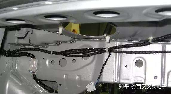
(1) According to the actual installation position of the wire harness on the vehicle, in order to avoid the wire harness from sagging or shifting, and considering the weight of the wire harness, the fixing method and the convenience of the fixing position, the wire harness must be fixed with sufficient and reasonable fixing points and fixing methods.
(2) Fixed points are set according to the direction of the wiring harness and the specific shape of the vehicle body. The distance between two fixed points on a straight line without a fulcrum is generally not more than 300 mm; one fixed point can be arranged at the obtuse turning point; two fixed points are required at the right-angle turning point; acute turning points should be avoided in the wiring harness.
(3) Select the type and size of the fixing buckle according to the shape and outer diameter of the wire harness, and make sure it can withstand the weight of the wire harness.
(4) Consider setting a fixing point at a suitable position no more than 120 mm in front of the connector where it is connected to other wiring harnesses and electrical components.
(5) Consider setting a fixed point on the main line at the fulcrum position, with the distance between the fixed point and the fulcrum no greater than 100 mm.
(6) There must be enough space in the installation direction of the fixed buckle to facilitate the installation and removal of the buckle.

2. Neat appearance and bundled configuration
(1) The wiring harness should be arranged along the edge and along the groove (the wiring groove designed on the body) to avoid direct pressure on the wiring harness. No wiring harness should be exposed in the cab; in the position where the wiring harness can be observed, such as: the cabin, set a striking attraction point or eye-catching color, and the wiring harness installed here will not be prominent or conspicuous.
(2) In the projection direction, the array should be arranged in a horizontal and vertical chessboard pattern, avoiding diagonal arrangement.
(3) The gap with the pipeline is uniform, and the gap with surrounding parts is reasonable.
In addition to paying attention to the layout of automotive wiring harnesses, it is also important to ensure that the wiring harnesses are safe and meet quality requirements during production and processing. When testing wiring harnesses, we generally choose a suitable wiring harness tester to conduct.
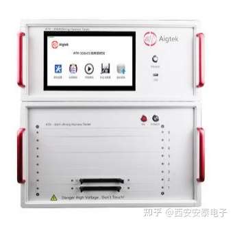
ATX-3000S Series Desktop Harness Tester

Insulation test detection voltage DC50V-750V
Withstand voltage test voltage AC50V-500V
Four-wire resistance test, minimum test accuracy 0.002 ohm
It has a self-learning function, can quickly detect the connection relationships such as the path, short circuit, and open circuit of the wiring harness, help users to compare and analyze data, and automatically record test reports. The maximum test points can reach 65536, and the channels can be quickly expanded. It is compatible with intelligent testing software and a large database. It can automatically reset after high-voltage detection, making cable testing safer.

Support WIFI wireless communication, RS232 control port, USB and other interfaces are optional, convenient peripheral connection, suitable for stand-alone operation or computer operation, equipped with win10 operating system and 10-inch multi-point capacitive touch screen, test operation is more convenient and full of technology.
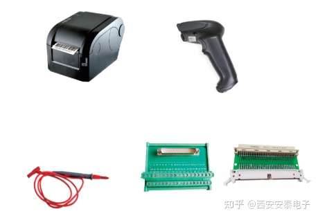
Optional accessories for the instrument include printer, probe, adapter plate, and calibration accessories.

Previous article:Introduction to the test principle of instantaneous disconnection detection of wiring harness tester
Next article:Application of cable tester in high voltage cable detection of new energy vehicles
- Popular Resources
- Popular amplifiers
- Modern manufacturing strategies drive continuous improvement in ICT online testing
- Methods for Correlation of Contact and Non-Contact Measurements
- Keysight Technologies Helps Samsung Electronics Successfully Validate FiRa® 2.0 Safe Distance Measurement Test Case
- From probes to power supplies, Tektronix is leading the way in comprehensive innovation in power electronics testing
- Seizing the Opportunities in the Chinese Application Market: NI's Challenges and Answers
- Tektronix Launches Breakthrough Power Measurement Tools to Accelerate Innovation as Global Electrification Accelerates
- Not all oscilloscopes are created equal: Why ADCs and low noise floor matter
- Enable TekHSI high-speed interface function to accelerate the remote transmission of waveform data
- How to measure the quality of soft start thyristor
- Intel promotes AI with multi-dimensional efforts in technology, application, and ecology
- ChinaJoy Qualcomm Snapdragon Theme Pavilion takes you to experience the new changes in digital entertainment in the 5G era
- Infineon's latest generation IGBT technology platform enables precise control of speed and position
- Two test methods for LED lighting life
- Don't Let Lightning Induced Surges Scare You
- Application of brushless motor controller ML4425/4426
- Easy identification of LED power supply quality
- World's first integrated photovoltaic solar system completed in Israel
- Sliding window mean filter for avr microcontroller AD conversion
- What does call mean in the detailed explanation of ABB robot programming instructions?
- Europe's three largest chip giants re-examine their supply chains
- Breaking through the intelligent competition, Changan Automobile opens the "God's perspective"
- The world's first fully digital chassis, looking forward to the debut of the U7 PHEV and EV versions
- Design of automotive LIN communication simulator based on Renesas MCU
- When will solid-state batteries become popular?
- Adding solid-state batteries, CATL wants to continue to be the "King of Ning"
- The agency predicts that my country's public electric vehicle charging piles will reach 3.6 million this year, accounting for nearly 70% of the world
- U.S. senators urge NHTSA to issue new vehicle safety rules
- Giants step up investment, accelerating the application of solid-state batteries
- Guangzhou Auto Show: End-to-end competition accelerates, autonomous driving fully impacts luxury...
- Using a single chip microcomputer to read out segment code LCD
- dsp28335 SCI Summary (Serial One-Step Communication)
- AT2401C Zigbee chip pin diagram and technical introduction
- How to read and decode the PPM signal of the RC remote control
- 【TouchGFX Design】graph waveform drawing
- C5000 compiles SUBC instruction to implement division
- [Project source code] Verilog language routine "Wang Jinming: "Verilog HDL Programming Tutorial""
- Introduction to Lin Protocol
- Deeply mourn comrade Paul Allen: march forward for his dream
- Recommend a micropython development software thonny

 LAYOUT_REPORT15-year summary of Taiwan\'s senior hardware engineer
 CVPR 2023 Paper Summary: Vision Applications and Systems


 京公网安备 11010802033920号