In aging tests, we often calculate the junction temperature based on the thermal resistance of the chip, the set furnace temperature, and the measured power consumption, and control the junction temperature within a safe range by adjusting the furnace temperature. The main test methods for package thermal resistance are infrared scanning, electrical measurement, transient thermal test interface method, and can also be obtained through simulation modeling. Infrared scanning is a direct test method, but it requires opening the chip cover and is destructive. The next two sections will discuss the measurement of thermal resistance based on two non-destructive tests: electrical measurement method and transient thermal test interface method.
Thermal resistance usually refers to the resistance encountered when heat flows through a thermal conductor (the temperature difference generated on the thermal conductor).
The common parameters defined by JEDEC are as follows:
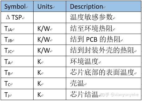
According to JESD51-1, the thermal resistance of a semiconductor device from junction to a reference point is:
: Semiconductor junction temperature
: Reference point temperature
: Thermal power consumption of semiconductors
Different thermal resistances can be defined by selecting different reference points according to actual needs.
Test methods and steps of measurement system
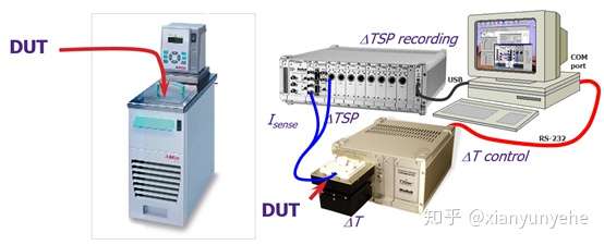
1) TSP determination. Generally, BJT selects base-emitter voltage , MOSFET selects source-drain voltage
, IGBT selects collector-emitter voltage
or gate-emitter voltage
, and diode selects forward voltage drop
as TSP.
2) Obtain the K coefficient. Measure the relationship between TSP and temperature to obtain the K coefficient. Taking the diode as an example, TSP is , place the device in a constant temperature environment, apply a test current to the device under test
, change the measurement temperature, and after the temperature stabilizes, measure the corresponding
, and establish
the corresponding relationship with the temperature.
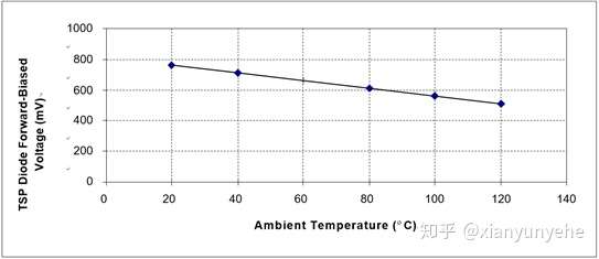
&
: High and low temperatures
&
= higher and lower
voltage
3) Measure junction temperature
There are two ways to test junction temperature electrically: static test and dynamic test.
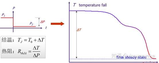
Static test:
Based on T3Ster's real-time acquisition, the test method complies with JESD51-1, JESD51-14 and IEC 60747 standards. Static testing is suitable for thermal testing chips.
a. Apply a heating current of magnitude to the device under test for a duration of
. When the device reaches thermal stability in the working state, remove the heating power and quickly switch the working current to the measurement current.
b. During the process of junction temperature drop, the junction voltage is sampled in real time, and then the junction temperature change over time is obtained through the K coefficient . The thermal resistance is calculated based on the temperature and power consumption change values.
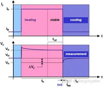

Dynamic Testing:
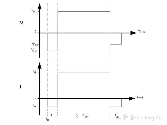
Dynamic testing is applicable to most integrated circuit devices. The test mainly includes three steps:
First, the test current is applied at the time
, then measured
and converted to the initial temperature using the K factor
.
Second, during the period, a heating current is applied
and measured
.
Third, turn off the power supply, apply the measurement current again , and measure
. The junction temperature change is calculated by multiplying the difference between
and by the K value. Adding them together gives the first temperature point .
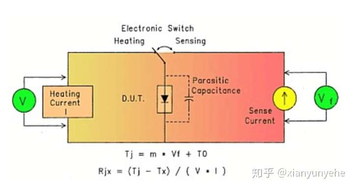
In the figure above, the switch is placed on the left for the heating process, and the switch is placed on the right for the test process. Apply the same heating current for different durations ( )
, and repeat the above steps to obtain the next data T2. Repeat continuously to establish a relationship diagram between junction temperature Ti and time. When Ti no longer changes, the junction temperature reaches a steady state. The corresponding thermal resistance calculated at this time is the steady-state thermal resistance, and the thermal resistance calculated at each time point before steady state is the transient thermal resistance.
Previous article:Method of testing distilled water (pure water) with a multimeter
Next article:Do you know how to operate the three major measuring instruments?
- Popular Resources
- Popular amplifiers
- Seizing the Opportunities in the Chinese Application Market: NI's Challenges and Answers
- Tektronix Launches Breakthrough Power Measurement Tools to Accelerate Innovation as Global Electrification Accelerates
- Not all oscilloscopes are created equal: Why ADCs and low noise floor matter
- Enable TekHSI high-speed interface function to accelerate the remote transmission of waveform data
- How to measure the quality of soft start thyristor
- How to use a multimeter to judge whether a soft starter is good or bad
- What are the advantages and disadvantages of non-contact temperature sensors?
- In what situations are non-contact temperature sensors widely used?
- How non-contact temperature sensors measure internal temperature
- LED chemical incompatibility test to see which chemicals LEDs can be used with
- Application of ARM9 hardware coprocessor on WinCE embedded motherboard
- What are the key points for selecting rotor flowmeter?
- LM317 high power charger circuit
- A brief analysis of Embest's application and development of embedded medical devices
- Single-phase RC protection circuit
- stm32 PVD programmable voltage monitor
- Introduction and measurement of edge trigger and level trigger of 51 single chip microcomputer
- Improved design of Linux system software shell protection technology
- What to do if the ABB robot protection device stops
- Apple faces class action lawsuit from 40 million UK iCloud users, faces $27.6 billion in claims
- Apple faces class action lawsuit from 40 million UK iCloud users, faces $27.6 billion in claims
- The US asked TSMC to restrict the export of high-end chips, and the Ministry of Commerce responded
- The US asked TSMC to restrict the export of high-end chips, and the Ministry of Commerce responded
- ASML predicts that its revenue in 2030 will exceed 457 billion yuan! Gross profit margin 56-60%
- Detailed explanation of intelligent car body perception system
- How to solve the problem that the servo drive is not enabled
- Why does the servo drive not power on?
- What point should I connect to when the servo is turned on?
- How to turn on the internal enable of Panasonic servo drive?
- ADI reference design geber file import ad problem
- Beijing's well-known 5G chip developer is recruiting: digital front-end engineer (RISCv or CPU digital front-end direction)
- Bike modification series: solar energy and batteries
- 【AT-START-F403A Review】Part 3 F403A STOP Mode Current Test
- [Free book 100% gift] A book teaches you how to develop test systems and gain an in-depth understanding of data acquisition systems
- 【DIY Creative LED】Circuit Analysis
- [DIY Bing Dun Dun] + a simple small Dun Dun board
- [RVB2601 Creative Application Development] 5. Initial test of RVB2601 WiFi networking and data interaction
- Participate in the PI energy-saving test, contribute the power of engineers, and protect the earth together!
- Bluetooth can be searched, but cannot connect

 ITT2112AH


 京公网安备 11010802033920号