In the brushless DC motor (BLDC) control system, the measurement of motor speed is an important and critical issue. There are many speed measurement methods: speed measurement using encoders, speed measurement using Hall (HALL) signals, speed measurement using motor back electromotive force, etc. Among them, the advantage of the encoder speed measurement method is that it can meet the requirements of high resolution, but it requires increased cost and volume; the advantage of using motor back electromotive force speed measurement is that there is no need to provide additional hardware interfaces, but the disadvantage is that the speed measurement software algorithm is complex. This article introduces a BLDC speed measurement software design scheme based on the NHET function of the TMS570 processor using HALL signals. This scheme can achieve a balance between speed measurement accuracy and the complexity of software and hardware. At the same time, an algorithm that improves reliability is used in the software design process to ensure the reliability and accuracy of speed measurement.
1 Introduction to TMS570 Processor and NHET Functions
The TMS570 series processor is a safety MCU launched by TI for the high-performance transportation field. This series of MCUs is based on the ARMCortex-R4F core architecture, has high performance and meets the safety requirements of IEC61508SIL-3. It is mainly used in the automotive industry, such as anti-lock braking system (ABS), electric power steering (EPS), and HEV/EV inverter systems.
The TMS570 series processors integrate the 4th generation high-end timer (NHET). NHET uses high-resolution hardware channels and provides accurate cycle and pulse measurement functions, output comparison functions, and PWM functions in real-time environments. NHET uses an independent instruction structure and a "timing resolution loop" mechanism to achieve a time resolution of ns level, fully meeting the needs of various high-precision time measurement applications. It integrates a programmable suppression filter to ensure the reliability of the measurement data.
2 BLDC speed measurement hardware interface design
The schematic diagram of the speed measurement hardware structure is shown in Figure 1. The design of the BLDC hardware speed measurement interface is relatively simple. After the HALL signal is digitally isolated, it can be directly connected to the NHET pin of TMS570. Introducing three HALL signals into NHET for speed measurement at the same time is a hardware redundancy design. Its purpose is to improve the reliability of BLDC speed measurement and prevent the failure of the entire speed measurement function due to the failure of a single-channel HALL input signal.
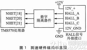
The HALL signal input uses a DC 12 V level, and after digital isolation, it outputs a DC 3.3 V level, which is directly used as the MCU input. When the BLDC rotates, the timing and phase relationship of the HALL signal is shown in Figure 2.
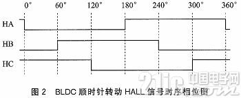
As shown in Figure 2, the BLDC speed can be calculated by measuring the frequency of a single HALL signal. The relationship between the BLDC speed (RPM, revolutions per minute) and the HALL signal frequency (fFO, Hz) and the BLDC pole pair number (Poles) is:

3 NHET speed measurement software design
The core speed measurement code of the NHET speed measurement software is implemented with an independent instruction structure and timing resolution mechanism. NHET adopts a reduced instruction set (RISC) structure, which contains 22 instructions. The NHET assembler is used to generate C language structure code from the instruction code, which needs to be copied to the NHET RAM by the application before running. The NHET assembler also generates a .h file, which is used by the application to access the measurement data. The timing mechanism is shown in Figure 3.
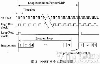
The NHET clock is driven by VCLK2. Each VCLK2 cycle is called a "time slot". After VCLK2 is divided by high resolution (High Res.clock) and loop frequency (Loop Res.clock), high-frequency division clock and loop frequency division clock are obtained. The periods of these two clocks are:

This program loop contains 1 to N NHET instructions. Since different instruction codes have different execution times, it should be noted during design that the sum of all code execution times within the program loop cannot exceed one cycle of the divided clock. As mentioned above, the rotation speed is measured using the Hall signal of the BLDC, that is, the cycle of the Hall signal is measured, which is implemented using the PCNT instruction in the NHET instruction set. The PCNT instruction captures the edge of the NHET input pin signal and uses a high-resolution clock to count the cycle, and stores the cycle time data in the internal register for the application to read. Taking the PCNT instruction to capture the input pulse signal time as an example, the instruction execution logic and timing are shown in Figure 4.
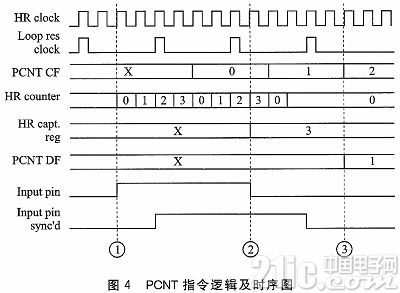
The meanings of ①~③ in Figure 4 are as follows:
① When the rising edge of the input pin is detected, the HR counter starts counting from zero. When the counter is full, 1 is added to the instruction data area and counting starts again from 0;
②When the falling edge of the input pin is detected, the data in the HR counter is stored in the capture register (HR capt.reg);
③The PCNT instruction starts to execute after the synchronous input signal (Input pin sync'd) changes from low to high. After the signal changes from high to low, the sum of the data area data (lr_data) and the data in the capture register (hr_data) is the pulse time.
The period of the HALL signal is the time from the rising edge to the falling edge or from the falling edge to the rising edge of the HALL input signal. The PCNT instruction parameters are as follows:
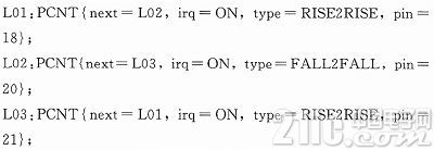
Each instruction corresponds to the HALL input signal of a channel. When the specified pin measures a complete HALL cycle, a NHET instruction interrupt (irq=ON) is generated. The signal trigger types include rising edge to rising edge (RISE2 RISE) and falling edge to falling edge (FALL2FALL). The purpose of using different signal trigger types to measure the HALL signal cycle is to ensure the reliability of the measurement results through simple software code heterogeneity.
When the VCLK2 clock is 70 MHz, select the high division frequency as 7 and the cyclic division frequency as 8, and we can get
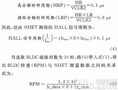
In order to prevent the measurement error of the HALL signal caused by external interference, in addition to using the hardware suppression filter of NHET itself, appropriate filtering should also be added in the software design process to ensure the accuracy and reliability of the measurement results. The C language code using a unipolar I2R low-pass filter with a coefficient of 0.75 is as follows:
new_speed=((old_speed*3U)+new_speed)>>2U;
//The newly measured speed accounts for 1/4 of the measurement result
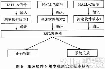
In order to improve the reliability of the speed measurement software, the software is designed with a structural fault-tolerant design idea. Since the speed measurement hardware uses 3-channel redundant acquisition of HALL input signals, the software adopts an N-version program design scheme. N-version program design means that for a given function, N (N>2) different design groups independently compile N different programs, and then run N different programs to obtain results and compare them to output correct data. The basic structure of the N-version program design of the TMS570 NHET function speed measurement software is shown in Figure 5.
Conclusion
This paper proposes a brushless DC motor speed measurement software design based on the NHET function of the TMS570 series processor, including the introduction of the NHET speed measurement principle and code implementation, the design of software filtering algorithm for measurement results, and the improvement of software reliability based on the N version software fault-tolerant design method. The speed measurement solution has been applied to the automatic door control unit hardware using the TMS570LS20216 processor. The results of actual tests and applications show that the solution is feasible.
Previous article:An intelligent pod ground detection system
Next article:Design of brake pad wear detection system based on CPCI image collector
- Popular Resources
- Popular amplifiers
- Seizing the Opportunities in the Chinese Application Market: NI's Challenges and Answers
- Tektronix Launches Breakthrough Power Measurement Tools to Accelerate Innovation as Global Electrification Accelerates
- Not all oscilloscopes are created equal: Why ADCs and low noise floor matter
- Enable TekHSI high-speed interface function to accelerate the remote transmission of waveform data
- How to measure the quality of soft start thyristor
- How to use a multimeter to judge whether a soft starter is good or bad
- What are the advantages and disadvantages of non-contact temperature sensors?
- In what situations are non-contact temperature sensors widely used?
- How non-contact temperature sensors measure internal temperature
- LED chemical incompatibility test to see which chemicals LEDs can be used with
- Application of ARM9 hardware coprocessor on WinCE embedded motherboard
- What are the key points for selecting rotor flowmeter?
- LM317 high power charger circuit
- A brief analysis of Embest's application and development of embedded medical devices
- Single-phase RC protection circuit
- stm32 PVD programmable voltage monitor
- Introduction and measurement of edge trigger and level trigger of 51 single chip microcomputer
- Improved design of Linux system software shell protection technology
- What to do if the ABB robot protection device stops
- CGD and Qorvo to jointly revolutionize motor control solutions
- CGD and Qorvo to jointly revolutionize motor control solutions
- Keysight Technologies FieldFox handheld analyzer with VDI spread spectrum module to achieve millimeter wave analysis function
- Infineon's PASCO2V15 XENSIV PAS CO2 5V Sensor Now Available at Mouser for Accurate CO2 Level Measurement
- Advanced gameplay, Harting takes your PCB board connection to a new level!
- Advanced gameplay, Harting takes your PCB board connection to a new level!
- A new chapter in Great Wall Motors R&D: solid-state battery technology leads the future
- Naxin Micro provides full-scenario GaN driver IC solutions
- Interpreting Huawei’s new solid-state battery patent, will it challenge CATL in 2030?
- Are pure electric/plug-in hybrid vehicles going crazy? A Chinese company has launched the world's first -40℃ dischargeable hybrid battery that is not afraid of cold
- DSP decimal conversion
- [Jihai APM32E103VET6S MINI Development Board Review] Part 5: Software Triggering ADC
- Huawei FPGA Design Complete Collection
- DC-DC output capability
- Here comes a smart home device controller that supports synchronous wireless communication. Let’s discuss it.
- Raspberry Pi Bluetooth Basics - Use of bluezero library
- "Recommended Chinese Chip" + JieFa AC781x ARM Chip
- 5 important attributes of EMC analysis
- Bandwidth Management System (BWM) for TI C64x+ DSPs
- Xunwei RK3399 development board supports installing Docker in Ubuntu system

 OPA121KM


 京公网安备 11010802033920号