bandwidth


Keywords:Oscilloscope
Reference address:Oscilloscope Things - Oscilloscope Bandwidth
Bandwidth determines the basic ability of an oscilloscope to measure signals. As the signal frequency increases, the oscilloscope's ability to accurately display the signal decreases. This indicator indicates the frequency range that the oscilloscope can accurately measure.
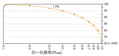
The bandwidth of an oscilloscope is the frequency at which a sinusoidal input signal is attenuated to the signal's true amplitude, known as the -3dB point. This term is based on a logarithmic scale, as shown in the figure.

The oscilloscope bandwidth is the frequency at which the sinusoidal input signal is attenuated to 70.7% of the actual amplitude of the signal, known as the -3dB point.
Without adequate bandwidth, the oscilloscope will not be able to resolve high frequency changes. Amplitudes will be distorted, edges will disappear, and details will be lost. Without adequate bandwidth, all the power and bells and whistles of an oscilloscope mean nothing.
To determine the oscilloscope bandwidth required to accurately characterize the signal amplitude in a particular application, the “rule of five” should be applied.
Oscilloscope bandwidth ≥ (highest frequency component of the signal × 5)
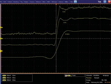
An oscilloscope selected using the rule of five will provide an error of less than ±2% in the measurement, which is generally adequate for current applications. However, as signal speeds increase, this rule of thumb may not be true. Keep in mind that the higher the bandwidth, the higher the signal reproduction that can be achieved, as shown in the figure.

The higher the bandwidth, the more accurate the signal reproduction. As shown in the figure, these are the signals captured at three bandwidth levels: 250MHz, 1GHz, and 4GHz.
Some oscilloscopes offer a way to enhance bandwidth through digital signal processing. You can use a DSP arbitrary equalization filter to improve the oscilloscope channel response. This filter expands the bandwidth, flattens the oscilloscope channel frequency response, improves phase linearity, and achieves better matching between channels. It also reduces the rise time and improves the time domain step response.
Summarize
This chapter introduces the bandwidth of the oscilloscope.
Previous article:Things about oscilloscopes - Oscilloscope acquisition rate
Next article:Things about Oscilloscopes - Probe Summary
Recommended Content
Latest Test Measurement Articles
- From probes to power supplies, Tektronix is leading the way in comprehensive innovation in power electronics testing
- Seizing the Opportunities in the Chinese Application Market: NI's Challenges and Answers
- Tektronix Launches Breakthrough Power Measurement Tools to Accelerate Innovation as Global Electrification Accelerates
- Not all oscilloscopes are created equal: Why ADCs and low noise floor matter
- Enable TekHSI high-speed interface function to accelerate the remote transmission of waveform data
- How to measure the quality of soft start thyristor
- How to use a multimeter to judge whether a soft starter is good or bad
- What are the advantages and disadvantages of non-contact temperature sensors?
- In what situations are non-contact temperature sensors widely used?
MoreSelected Circuit Diagrams
MorePopular Articles
- LED chemical incompatibility test to see which chemicals LEDs can be used with
- Application of ARM9 hardware coprocessor on WinCE embedded motherboard
- What are the key points for selecting rotor flowmeter?
- LM317 high power charger circuit
- A brief analysis of Embest's application and development of embedded medical devices
- Single-phase RC protection circuit
- stm32 PVD programmable voltage monitor
- Introduction and measurement of edge trigger and level trigger of 51 single chip microcomputer
- Improved design of Linux system software shell protection technology
- What to do if the ABB robot protection device stops
MoreDaily News
- Analysis of the application of several common contact parts in high-voltage connectors of new energy vehicles
- Wiring harness durability test and contact voltage drop test method
- From probes to power supplies, Tektronix is leading the way in comprehensive innovation in power electronics testing
- From probes to power supplies, Tektronix is leading the way in comprehensive innovation in power electronics testing
- Sn-doped CuO nanostructure-based ethanol gas sensor for real-time drunk driving detection in vehicles
- Design considerations for automotive battery wiring harness
- Do you know all the various motors commonly used in automotive electronics?
- What are the functions of the Internet of Vehicles? What are the uses and benefits of the Internet of Vehicles?
- Power Inverter - A critical safety system for electric vehicles
- Analysis of the information security mechanism of AUTOSAR, the automotive embedded software framework
Guess you like
- "Recommend Chinese chips" + domestic chips
- 【NXP Rapid IoT Review】 NO3. Receiving data from the cloud
- Littelfuse Efficient, Reliable, Accurate Power Control and Circuit Protection Solutions
- What issues need to be considered when using MCU development boards as industrial application boards
- INA128 Instrument Amplifier
- EEWORLD University Hall ---- FPGA Tips for Ming Deyang
- About GD32E230I2C as a slave
- With Trump's propaganda, RF has become extremely popular in the past two years. There are articles everywhere to share.
- [Liquid Level Sensor Evaluation] Sensor Performance Comparison (and Final Report)
- Bluetooth Technology Principle

 Signal Integrity and Power Integrity Analysis (Eric Bogatin)


 京公网安备 11010802033920号