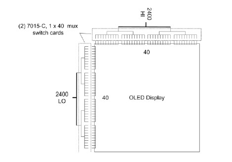
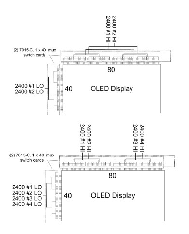
Testing a display consisting of an array of pixels requires automated signal routing to switch power to the pixels under test. A GPIB-controlled switch system, such as the 7002, can control the internal 2D relay switch scanner card. The block diagram in Figure 1 shows how two multiplex scanner cards can be connected to a display under test to form a 40×40 array. In this example, only one Model 2400 SourceMeter was used, and a Model 7015-C 1×40 two-pole solid-state relay multiplexer card was also used. The 7015-C is a solid-state relay switch with a switching time of less than 500 microseconds to ensure maximum test throughput. When using the Model 2400 SourceMeter, the bias current of each scanner card is much less than 1nA, allowing leakage current measurements to be accurate to 10-8-10-9A. In a test system using only one source meter, all relays connected to rows and columns on the scan card only need to be single-pole, connecting the "high" or "low" end to the display rows and columns.

Keywords:OLED
Reference address:Important electrical indicators in DC production testing of OLED displays (Part 2)

Previous article:Important electrical indicators in DC production testing of OLED displays (I)
Next article:Important electrical parameters in DC production testing of OLED displays (Part 3)
- Popular Resources
- Popular amplifiers
Recommended Content
Latest Test Measurement Articles
- Seizing the Opportunities in the Chinese Application Market: NI's Challenges and Answers
- Tektronix Launches Breakthrough Power Measurement Tools to Accelerate Innovation as Global Electrification Accelerates
- Not all oscilloscopes are created equal: Why ADCs and low noise floor matter
- Enable TekHSI high-speed interface function to accelerate the remote transmission of waveform data
- How to measure the quality of soft start thyristor
- How to use a multimeter to judge whether a soft starter is good or bad
- What are the advantages and disadvantages of non-contact temperature sensors?
- In what situations are non-contact temperature sensors widely used?
- How non-contact temperature sensors measure internal temperature
MoreSelected Circuit Diagrams
MorePopular Articles
- LED chemical incompatibility test to see which chemicals LEDs can be used with
- Application of ARM9 hardware coprocessor on WinCE embedded motherboard
- What are the key points for selecting rotor flowmeter?
- LM317 high power charger circuit
- A brief analysis of Embest's application and development of embedded medical devices
- Single-phase RC protection circuit
- stm32 PVD programmable voltage monitor
- Introduction and measurement of edge trigger and level trigger of 51 single chip microcomputer
- Improved design of Linux system software shell protection technology
- What to do if the ABB robot protection device stops
MoreDaily News
- CGD and Qorvo to jointly revolutionize motor control solutions
- CGD and Qorvo to jointly revolutionize motor control solutions
- Keysight Technologies FieldFox handheld analyzer with VDI spread spectrum module to achieve millimeter wave analysis function
- Infineon's PASCO2V15 XENSIV PAS CO2 5V Sensor Now Available at Mouser for Accurate CO2 Level Measurement
- Advanced gameplay, Harting takes your PCB board connection to a new level!
- Advanced gameplay, Harting takes your PCB board connection to a new level!
- A new chapter in Great Wall Motors R&D: solid-state battery technology leads the future
- Naxin Micro provides full-scenario GaN driver IC solutions
- Interpreting Huawei’s new solid-state battery patent, will it challenge CATL in 2030?
- Are pure electric/plug-in hybrid vehicles going crazy? A Chinese company has launched the world's first -40℃ dischargeable hybrid battery that is not afraid of cold
Guess you like
- Can SDRAM chips be used on 2-layer boards?
- Let Arduino play with your useless STM32 board Part 2
- Even Huawei can’t hold on?
- About FlashBurn can not burn
- LED transparent screen signal transmission method
- The compiler keeps reporting an error, saying there is an error here. I have looked at it many times but can't find where the problem is.
- MicroPython makes several more improvements to Bluetooth
- The mastery of analog circuits is divided into three levels
- TI Automotive Headlight LED Lighting System (Single Stage) Solution
- Application of INA series current detection devices in TWS battery box


 LM709CN


 京公网安备 11010802033920号