When using CBN diamond grinding wheels for grinding operations, in addition to the very important service life of the grinding wheel, it is also crucial to understand the quality factors of the grinding wheel in order to meet the high requirements for the grinding process and processing accuracy.
The grinding process has always played a very important role in the processing of tools and components. Compared with other types of cutting technologies, the advantages of the grinding process are its good machinability for hard materials, high geometric tolerance accuracy (IT5~6) and small ripples and roughness of the grinding surface (Rz=1~3μm).
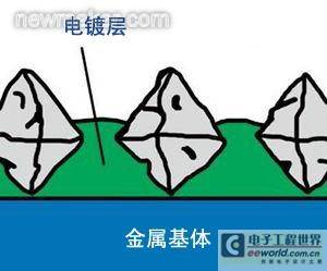
Since the basic shape of the electroplated grinding wheel is highly plastic and easy to cut, this process is particularly suitable for processing occasions with higher requirements. The characteristic of the electroplating layer of the grinding wheel is that on the one hand, the wear limit range requirements need to be met through high-quality grinding particles, and on the other hand, space for chip discharge needs to be left.
Overall observation of the grinding process
As the processing technology becomes more and more complex, the grinding process must be observed as a whole. This means that specific requirements should be put forward for the configuration of the grinding wheel used according to various different applications. This often involves the problem of surface shape (i.e. the effective area of the cutter head). In order to be able to characterize and evaluate the relevant surfaces in detail, modern measuring technologies and methods must be used. This allows an objective assessment of the results and quality level of the tool process with particles at any point in time. This is also a prerequisite for ensuring stable machining quality.
Material load ratio is an important detection feature
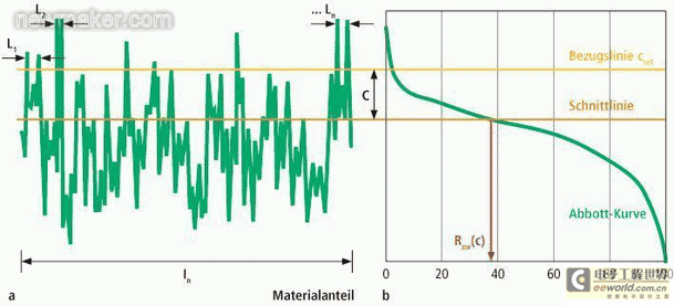
Another important detection feature for the evaluation of grinding wheel quality is the material load ratio and the material ratio curve (Abbott curve), as shown in Figure 2. The material load ratio reflects the percentage of the grinding wheel surface below this value in the 3D section at a certain value. This parameter is very important for the evaluation of the relationship between the use of the grinding wheel and the specific processing task. As part of a research project, a non-contact measuring technique for determining the material load ratio was developed in cooperation between the two companies FGW Remscheid eV and GFE Schmalkalden eV with the participation of a coordination committee. In order to validate this measuring technique, a correlation study was carried out between the measurement results obtained with electroplated grinding wheels and the machining results.
The second step is to conduct a correlation study of the grinding wheel processing results. For this purpose, realistic wear states are generated using reproducible parameter sets and a series of grinding tests are carried out. Compensation is then achieved by electronic raster and microphotographic measurement of tool and workpiece characteristics, based on novel optoelectronic structures and using the results of newly developed image processing technology. This repetitive process can be used to verify the correlation between the measured material load ratio and the actual grinding wheel processing result, and the function and usability of the image collection method can also be verified with the help of the instrument.
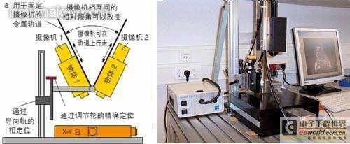
As a result, a non-contact technical process for determining the material load ratio of electroplated grinding wheels was developed within the research project. The instrumental basis for this work is a test bench that combines stereomicroscopy and confocal microscopy.
The economic advantage of this method for companies lies in the rapid characterization of the surface state. The test bench allows the material ratio curve of the tool to be determined quickly, simply, reproducibly and documented. The knowledge gained helps users to continue to develop their products. (end)
Reference address:Quickly determine the quality of CBN grinding wheels
The grinding process has always played a very important role in the processing of tools and components. Compared with other types of cutting technologies, the advantages of the grinding process are its good machinability for hard materials, high geometric tolerance accuracy (IT5~6) and small ripples and roughness of the grinding surface (Rz=1~3μm).
Since the basic shape of the electroplated grinding wheel is highly plastic and easy to cut, this process is particularly suitable for processing occasions with higher requirements. The characteristic of the electroplating layer of the grinding wheel is that on the one hand, the wear limit range requirements need to be met through high-quality grinding particles, and on the other hand, space for chip discharge needs to be left.
Overall observation of the grinding process
As the processing technology becomes more and more complex, the grinding process must be observed as a whole. This means that specific requirements should be put forward for the configuration of the grinding wheel used according to various different applications. This often involves the problem of surface shape (i.e. the effective area of the cutter head). In order to be able to characterize and evaluate the relevant surfaces in detail, modern measuring technologies and methods must be used. This allows an objective assessment of the results and quality level of the tool process with particles at any point in time. This is also a prerequisite for ensuring stable machining quality.

Material load ratio is an important detection feature
Another important detection feature for the evaluation of grinding wheel quality is the material load ratio and the material ratio curve (Abbott curve), as shown in Figure 2. The material load ratio reflects the percentage of the grinding wheel surface below this value in the 3D section at a certain value. This parameter is very important for the evaluation of the relationship between the use of the grinding wheel and the specific processing task. As part of a research project, a non-contact measuring technique for determining the material load ratio was developed in cooperation between the two companies FGW Remscheid eV and GFE Schmalkalden eV with the participation of a coordination committee. In order to validate this measuring technique, a correlation study was carried out between the measurement results obtained with electroplated grinding wheels and the machining results.


The second step is to conduct a correlation study of the grinding wheel processing results. For this purpose, realistic wear states are generated using reproducible parameter sets and a series of grinding tests are carried out. Compensation is then achieved by electronic raster and microphotographic measurement of tool and workpiece characteristics, based on novel optoelectronic structures and using the results of newly developed image processing technology. This repetitive process can be used to verify the correlation between the measured material load ratio and the actual grinding wheel processing result, and the function and usability of the image collection method can also be verified with the help of the instrument.
As a result, a non-contact technical process for determining the material load ratio of electroplated grinding wheels was developed within the research project. The instrumental basis for this work is a test bench that combines stereomicroscopy and confocal microscopy.
The economic advantage of this method for companies lies in the rapid characterization of the surface state. The test bench allows the material ratio curve of the tool to be determined quickly, simply, reproducibly and documented. The knowledge gained helps users to continue to develop their products. (end)
Previous article:Research on aircraft shape and position error detection technology
Next article:Non-contact and high-precision measurement of tools using lasers
- Popular Resources
- Popular amplifiers
Recommended Content
Latest Test Measurement Articles
- New IsoVu™ Isolated Current Probes: Bringing a New Dimension to Current Measurements
- Modern manufacturing strategies drive continuous improvement in ICT online testing
- Methods for Correlation of Contact and Non-Contact Measurements
- Keysight Technologies Helps Samsung Electronics Successfully Validate FiRa® 2.0 Safe Distance Measurement Test Case
- From probes to power supplies, Tektronix is leading the way in comprehensive innovation in power electronics testing
- Seizing the Opportunities in the Chinese Application Market: NI's Challenges and Answers
- Tektronix Launches Breakthrough Power Measurement Tools to Accelerate Innovation as Global Electrification Accelerates
- Not all oscilloscopes are created equal: Why ADCs and low noise floor matter
- Enable TekHSI high-speed interface function to accelerate the remote transmission of waveform data
MoreSelected Circuit Diagrams
MorePopular Articles
- Intel promotes AI with multi-dimensional efforts in technology, application, and ecology
- ChinaJoy Qualcomm Snapdragon Theme Pavilion takes you to experience the new changes in digital entertainment in the 5G era
- Infineon's latest generation IGBT technology platform enables precise control of speed and position
- Two test methods for LED lighting life
- Don't Let Lightning Induced Surges Scare You
- Application of brushless motor controller ML4425/4426
- Easy identification of LED power supply quality
- World's first integrated photovoltaic solar system completed in Israel
- Sliding window mean filter for avr microcontroller AD conversion
- What does call mean in the detailed explanation of ABB robot programming instructions?
MoreDaily News
- STMicroelectronics discloses its 2027-2028 financial model and path to achieve its 2030 goals
- 2024 China Automotive Charging and Battery Swapping Ecosystem Conference held in Taiyuan
- State-owned enterprises team up to invest in solid-state battery giant
- The evolution of electronic and electrical architecture is accelerating
- The first! National Automotive Chip Quality Inspection Center established
- BYD releases self-developed automotive chip using 4nm process, with a running score of up to 1.15 million
- GEODNET launches GEO-PULSE, a car GPS navigation device
- Should Chinese car companies develop their own high-computing chips?
- Infineon and Siemens combine embedded automotive software platform with microcontrollers to provide the necessary functions for next-generation SDVs
- Continental launches invisible biometric sensor display to monitor passengers' vital signs
Guess you like
- AT91SAM7S64 Debugging Notes
- Implementation of Ethernet communication between TI C6678 DSP and PC
- Design of a practical computer multi-point temperature detection system
- [ESP32 Learning] Comparison of file reading speeds of two SDIO methods
- [GD32F350 sharing] [V] GY-30 light intensity module driver writing
- I2C Protocol (Official English Version)
- MYZR-RK3288 compile source code
- stm8
- Grab and run! EPOS implementation in unmanned retail stores
- 【ESP32 Learning】Using TF Card

 Practical Technology of Electromagnetic Compatibility Design and Testing


 京公网安备 11010802033920号