With the development of digital engineering in the aircraft manufacturing industry, digital manufacturing has become the direction of production and development of our aviation enterprises. This requires CNC detection technology to adapt to it and realize digital detection of products to meet the rapid development and quality requirements of scientific research and production. Foreign advanced aviation companies such as Boeing, Airbus and other large aviation manufacturing companies have used digital detection technology in CNC measurement. In the measurement of form and position tolerances, only the detection function of the measuring machine is used for measurement, and the measurement principle is not deeply understood. The measurement is completely dependent on the software function of the measuring machine, and its CNC detection ability is not fully utilized. The measurement software evaluates the form and position errors, and its measurement results can only provide a quantitative error value, and cannot indicate the deviation direction in a directional manner. For example, when measuring symmetry, its measurement results can only quantitatively reflect the value of the symmetry deviation, and cannot directionally reflect the direction of the symmetry deviation; when using the measurement software function to detect the contour, its results can only reflect the contour error of the entire surface, and cannot accurately reflect the value of the specific part of the deviation. Therefore, directly using the measuring machine function for detection is neither convenient for product repair nor for product quality analysis. Therefore, it is necessary to study its digital detection technology and realize the digital detection of form and position tolerances.
Combined with the characteristics of three-dimensional coordinate measurement, digital detection of geometric tolerances is studied, and the corresponding part coordinate system is established. The coordinate value of the point can intuitively reflect the quality of the entire shape and deviation direction of the physical object. This is convenient for the repair of unqualified products and for the process department to analyze product quality more accurately, promoting the improvement of process methods. The level of digital detection directly affects the quality and delivery progress of the product. Therefore, it is of great practical significance to study product digital detection technology and improve work efficiency and product quality.
The research on surface profile detection technology
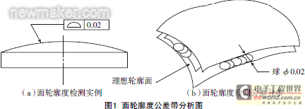
is shown in Figure 1. The surface profile tolerance zone is the area between the two enveloping surfaces of a series of balls with a diameter of 0.200mm and a tolerance value. The centers of the balls should be located on the surface with the theoretically correct geometric shape. When the ideal contour of the measured element has no position requirement relative to the reference, it belongs to the shape tolerance; when the ideal contour of the measured element has a position requirement for the reference, it belongs to the position tolerance [1].
When the surface profile is a shape error, the coordinate value of the measured point can be used to best fit the surface to achieve the optimal state of all measured points and perform the final point assessment.
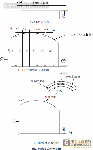
When the surface profile is a position error, according to the coordinate value of the measuring point, no translation or rotation can be performed in the given position direction (on the marked datum), and any translation and rotation can be performed in other directions until all points reach the optimal state, and the final point evaluation is performed. The profile tolerance analysis is shown in Figure 2.
According to the layout requirements of the surface feature points, the theoretical point data of the measured part is extracted on the product model. The automatic detection function of the vector point is used to measure these points, and the total error of the point is calculated using formula (1). The deviation of the measured contour from the ideal contour can also be analyzed by observing the coordinate value of each actual measured point.
Research on the detection technology of line contour
At present, when evaluating complex line contour, optimization algorithms such as Newton iteration method are often used to calculate the nearest distance between the measured point and the theoretical contour line. The calculation process is complicated and even cannot be solved in some cases. In addition, when the entire contour curve is composed of multiple expressions, it is necessary to first determine the contour expression corresponding to the measured point; for the contour with a series of type value points, functions such as cubic spline are often used to fit the theoretical contour. After obtaining the fitted theoretical contour expression, the contour error of the measured point is calculated according to the previous method. The fitting process will inevitably result in accuracy loss [3].
In view of the cumbersomeness and limitations of the current line profile evaluation method, this paper proposes a profile evaluation algorithm based on discrete points. The algorithm mainly calculates the minimum distance between points, avoiding the more difficult calculation of the minimum distance between points and irregular curves.
Line profile error refers to the variation of the actual measured contour line to the theoretical contour line. According to the definition of profile error, the most basic evaluation principle needs to meet the minimum inclusion area principle. The minimum inclusion area refers to the inclusion area with the minimum width when the actual contour line is included by two parallel curves. In the evaluation of line profile error, any method must take this principle as the basic principle, but because it is difficult to directly adopt this principle, approximate algorithms such as least squares are often used. The evaluation of line profile can be divided into line profile with benchmark requirements and line profile without benchmark requirements based on whether there is a benchmark. This paper takes the line profile with benchmark requirements as an example to discuss the profile algorithm based on discrete points, which is also applicable to line profile without benchmark requirements.
When the line profile is required to be evaluated only in any direction, its actual measurement requirements are basically the same as those of the surface profile. However, when the line profile is required to be evaluated in any direction and within a specified length, its actual measurement requirements are somewhat different from those of the surface profile detection. During the detection and evaluation, the length of the arbitrary curve must be controlled. The line profile is evaluated within the specified length. Such requirements are looser than the relative tolerance requirements for evaluating the length without specifying the length. This paper mainly discusses the method of evaluating the line profile in any direction and within the specified length.
According to the theoretical coordinate values and theoretical normal vectors of the discrete points obtained, combined with the automatic point measurement function of the three-dimensional coordinate measuring machine, all theoretical discrete points are automatically detected to obtain the actual measurement values of these theoretical discrete points.
The discrete points are used to evaluate the line profile, that is, the discrete points P of the theoretical profile are compared and calculated with the discrete points Q of the measured profile. First, for each Q, a point closest to it is searched in P. Secondly, the minimum distance d corresponding to each Q is calculated. Finally, the maximum value dmax in the series is calculated, that is, the line profile error of the measured profile. [page]
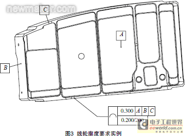
As shown in Figure 3, the line profile is marked on the curved surface. In the lower frame, the line profile requires that the line profile tolerance is 0.200mm along any direction and any 200mm length of the measured surface. Currently, CMM measurement software only evaluates the line profile within a certain plane and cannot evaluate the line profile error along any direction.
Assuming that a certain curve has three measuring points A, B, and C, calculate the errors of the three points A, B, and C. If the error is greater than the tolerance, it is unqualified, and if it is less than the tolerance, it is qualified. However, the number of measurement points cannot be determined in advance. Therefore, another equivalent method can be used, that is, the two-point comparison method is used instead of the three-point or more point comparison method. For example, the error value of the three points (A, B, C) must be one of the three error values of (A, B), (A, C), and (B, C). If one of them is unqualified, it is unqualified, and if all are qualified, it is qualified. There are
countless planes passing through any two points, and each plane has an intersection line with the surface. Therefore, it is impossible to determine the distance between the two points on the curve. The straight-line distance between the two points can only be used instead of the curve distance. This not only can better control the line profile, but also makes the algorithm feasible. The main interface of the line profile data evaluation program is shown in Figure 4.
Composite position tolerance provides a way to apply position tolerance on the positioning of feature size groups and the relationship between feature sizes within the group (constrained rotation and translation). The requirements are indicated by using a composite feature control frame.
For this type of position, the position symbol is filled in only once and applies to all horizontal frames. Each complete horizontal frame in the feature control frame can be checked separately.
Composite position measurement includes group positioning tolerance band frame and feature related tolerance band frame. The
tolerance band frame of the group positioning tolerance band frame constrains the rotation and translation relative to the specified datum. A larger position tolerance is specified for the feature size group as a group positioning. Applicable datum features should be referenced in a given priority order and play a role in linking the theoretically correct dimension to the datum reference frame.
Feature related tolerance band frames are controlled by feature relatedness. They control the smaller position tolerance of each feature dimension within the group (the relationship between features). Basic dimensions can be used for group positioning tolerance band frames, but not for feature related tolerance band frames.
When no reference datum is specified in the lower cell of the composite feature control frame, the feature-dependent tolerance zone frame can rotate and translate freely within the boundaries established and controlled by the group position tolerance zone frame; if datums are specified in the lower cell, they control the rotation of the feature-dependent tolerance zone frame relative to the datum within the boundaries established and controlled by the group position tolerance zone frame; when datum feature references are specified, one or more datum features specified in the top cell of the position tolerance frame should constrain the rotation of the coordinate system in the same priority order.
Composite tolerances have two or more cells. Each cell establishes tolerance zones and constrains any reference datums displayed in the cell. Reference datums in the first cell establish all applicable rotational and translational constraints relative to the referenced datum. Reference datums in the second and subsequent cells only establish rotational constraints relative to the referenced datum.
When reference datums in a cell are empty, it means that no rotational and translational constraints are established through those cells. For the application of a group feature with a composite position tolerance, the group position tolerance zone is established through the first cell, and the individual feature-dependent tolerance zones are established through each subsequent cell.
For example, the upper grid for measuring the hole position is relative to the A, B, C datum position, and the tolerance requirement is φ0.25; the lower grid is relative to the A, B, C datum position, and the tolerance requirement is φ 0.10;
for the upper grid position detection, after the coordinate system is established according to the A, B, C datum, the position is directly evaluated according to the relationship between its characteristic elements and the datum, and rotation and translation relative to the A, B, C datum are not allowed.
For the lower grid position detection, after the coordinate system is established according to the A, B, C datum, the position is evaluated according to the dimensional relationship between its characteristic elements, and rotation relative to the A, B, C datum is not allowed.
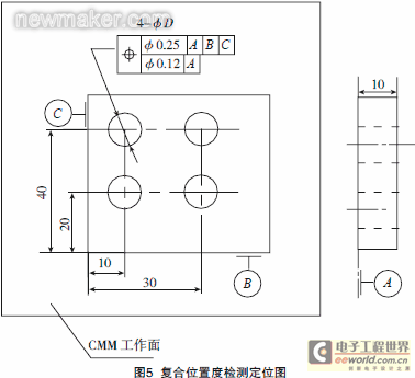
Tolerance zone: As shown in Figure 5, the tolerance value is preceded by the symbol φ indicating the diameter, and the shape of the position tolerance zone is a cylinder; during measurement, the position error of the hole is mainly controlled by measuring the position error of the two extreme points of the hole. When the position error of the two extreme points of the hole is qualified, the position of the hole is qualified. When evaluating the error, let the theoretical coordinates of the center of each circle be oi(xi, yi zi), and the actual coordinates of the center of the circle be Oi(Xi, Yi Zi), then the position error of the limit points at both ends of each hole is expressed as =2(Xi-xi)2+ (Yi-yi)2.
The following example illustrates the detection method of composite position.
The detection process is as follows:
Step 1: Properly position the part to be measured on the workbench of the three-dimensional coordinate measuring machine (CMM work surface), as shown in Figure 5.
Step 4: Measure the contour of the cylinder, and fit the cylinder with the actual points on each cylindrical surface, and fit 4 cylinders in total.
Step 5: Construct the two end faces of the cylinder, and intersect the measured cylinder with the two end planes to obtain 8 limit points.
Step 6: In the 1# coordinate system, by observing the coordinate value of each limit point, the deviation state of the measured hole relative to the datum can be analyzed, and the distance is calculated by the actual position and theoretical position of each limit point. The twice of this distance is the position error of each measured hole relative to the datum A, B, and C. [page]
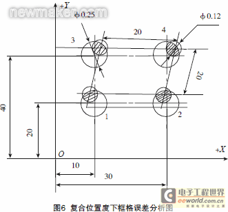
Calculate the position error of the lower frame, and the measurement of the lower frame with the datum is shown in Figure 6.
Step 7: In the 1# coordinate system, establish the X\' axis direction with the construction lines of holes 1 and 2, define hole 1 X=10, Y=20, and this coordinate system is the 2# coordinate system.
Step 8: In the 2# coordinate system, by observing the coordinate values of each limit point, the deviation state between the measured holes can be analyzed, and the distance is calculated by the actual position and theoretical position of each limit point. The double of this distance is the position error between each measured hole.
When the position of the lower frame is out of tolerance, the 2# coordinate system can be arbitrarily translated or rotated on the premise that the position of the upper frame is qualified until the position of the lower frame reaches the optimal state.
When the upper frame position and the lower frame position are both qualified, the composite position is qualified, otherwise the composite position is unqualified.
Other commonly used position measurements in the research of position measurement technology
include coaxiality, symmetry, parallelism, verticality, inclination, etc. The principle of using a three-dimensional coordinate measuring machine for digital detection is to convert these abstract geometric error measurements into corresponding point control evaluations, and calculate the corresponding position evaluation results based on their corresponding position algorithm.
For example, the measurement of symmetry:
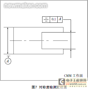
Symmetry refers to the condition in which two central symmetrical elements on a part remain in the same plane. The symmetry tolerance is the maximum allowable variation of the measured element relative to the reference element. There are many symmetrical structural elements on a part, such as the two sides of a keyway, a V-groove, the two sides of a connecting rod slider, and the surface of a rotating body [5]. The
following example illustrates the detection of symmetry on a three-dimensional coordinate measuring machine.
(1) Tolerance zone: The symmetry tolerance zone of the measured plane is the area between two parallel planes that are symmetrically arranged relative to the reference center plane and have a distance of 0.1 mm, as shown in Figure 7.
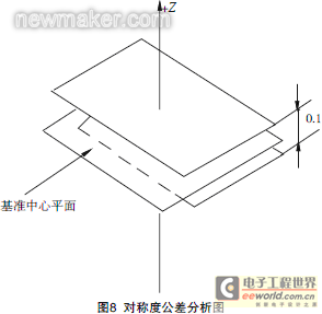
Step 1: Properly position the measured part on the workbench of the three-dimensional coordinate measuring machine (CMM work surface), as shown in Figure 8.
Step 3: Measure the contour of the surface to obtain the actual point position.
Step 4: According to the type of tolerance zone, the Z-direction tolerance of these points can be assigned as: +0.05/-0.05.
Step 5: By observing the Z-direction coordinate value of each actual point, it is possible to determine whether the symmetry is qualified, and the deviation state of the measured plane relative to the datum plane can also be analyzed.
The method for composite surface profile is basically the same as that for composite position, which mainly converts the surface profile into vector point detection. The application of the datum annotation in the establishment of the measurement coordinate system is the same as that of the composite position.
Conclusion
The concept of digitization has been widely promoted and applied in the processing and manufacturing industry. Although the measurement results can be quantitatively obtained by simply using the measuring machine software function for product inspection, the measurement results are not convenient for subsequent process analysis. The digital detection of geometric tolerances is studied, and a method of evaluating geometric errors using discrete point detection is proposed, which intuitively reflects the quality and deviation direction of the entire shape of the object. It is not only convenient for the repair of defective products, but also can promote the improvement of process methods, with potential economic benefits.
Complex geometric errors have been widely used in international design concepts, and some complex geometric errors are also used in the latest designs in China. However, there is no clear explanation for the concept of some complex geometric errors, such as composite surface profile, line profile evaluated within a specified range, etc. We need to study and learn, deeply understand its concept and evaluation method, and then develop its corresponding detection method.
References
[1] Zhang Xuechang. Research on key technologies for digital detection of complex surfaces based on point cloud data and its system development [D]. Shanghai: Shanghai Jiaotong University, 2006.
[2] Pfeiffer A. Dasta analysis in the grid.era, nuclear symposium conference record, 2003 IEEE, 2003: 22-25.
[3] Hou Yu, Zhang Jing, Cui Chenyang. Data processing method for coordinate measurement of complex line profile error. Journal of Metrology, 2002(1):1-3.
[4] Zhang Jin, Wang Zhong, Li Chao, et al. Line profile evaluation algorithm for discrete points. Optical Precision Engineering, 2008(11):2281-2285.
[5] Xu Xiandong, Song Shuwen. Data processing of geometric and positional errors. China Measurement Technology, 2004(4):1-3. (end)
Reference address:Research on aircraft shape and position error detection technology
Combined with the characteristics of three-dimensional coordinate measurement, digital detection of geometric tolerances is studied, and the corresponding part coordinate system is established. The coordinate value of the point can intuitively reflect the quality of the entire shape and deviation direction of the physical object. This is convenient for the repair of unqualified products and for the process department to analyze product quality more accurately, promoting the improvement of process methods. The level of digital detection directly affects the quality and delivery progress of the product. Therefore, it is of great practical significance to study product digital detection technology and improve work efficiency and product quality.
The research on surface profile detection technology
is shown in Figure 1. The surface profile tolerance zone is the area between the two enveloping surfaces of a series of balls with a diameter of 0.200mm and a tolerance value. The centers of the balls should be located on the surface with the theoretically correct geometric shape. When the ideal contour of the measured element has no position requirement relative to the reference, it belongs to the shape tolerance; when the ideal contour of the measured element has a position requirement for the reference, it belongs to the position tolerance [1].
When the surface profile is a shape error, the coordinate value of the measured point can be used to best fit the surface to achieve the optimal state of all measured points and perform the final point assessment.
When the surface profile is a position error, according to the coordinate value of the measuring point, no translation or rotation can be performed in the given position direction (on the marked datum), and any translation and rotation can be performed in other directions until all points reach the optimal state, and the final point evaluation is performed. The profile tolerance analysis is shown in Figure 2.
According to the layout requirements of the surface feature points, the theoretical point data of the measured part is extracted on the product model. The automatic detection function of the vector point is used to measure these points, and the total error of the point is calculated using formula (1). The deviation of the measured contour from the ideal contour can also be analyzed by observing the coordinate value of each actual measured point.
Research on the detection technology of line contour
At present, when evaluating complex line contour, optimization algorithms such as Newton iteration method are often used to calculate the nearest distance between the measured point and the theoretical contour line. The calculation process is complicated and even cannot be solved in some cases. In addition, when the entire contour curve is composed of multiple expressions, it is necessary to first determine the contour expression corresponding to the measured point; for the contour with a series of type value points, functions such as cubic spline are often used to fit the theoretical contour. After obtaining the fitted theoretical contour expression, the contour error of the measured point is calculated according to the previous method. The fitting process will inevitably result in accuracy loss [3].
In view of the cumbersomeness and limitations of the current line profile evaluation method, this paper proposes a profile evaluation algorithm based on discrete points. The algorithm mainly calculates the minimum distance between points, avoiding the more difficult calculation of the minimum distance between points and irregular curves.
Line profile error refers to the variation of the actual measured contour line to the theoretical contour line. According to the definition of profile error, the most basic evaluation principle needs to meet the minimum inclusion area principle. The minimum inclusion area refers to the inclusion area with the minimum width when the actual contour line is included by two parallel curves. In the evaluation of line profile error, any method must take this principle as the basic principle, but because it is difficult to directly adopt this principle, approximate algorithms such as least squares are often used. The evaluation of line profile can be divided into line profile with benchmark requirements and line profile without benchmark requirements based on whether there is a benchmark. This paper takes the line profile with benchmark requirements as an example to discuss the profile algorithm based on discrete points, which is also applicable to line profile without benchmark requirements.
When the line profile is required to be evaluated only in any direction, its actual measurement requirements are basically the same as those of the surface profile. However, when the line profile is required to be evaluated in any direction and within a specified length, its actual measurement requirements are somewhat different from those of the surface profile detection. During the detection and evaluation, the length of the arbitrary curve must be controlled. The line profile is evaluated within the specified length. Such requirements are looser than the relative tolerance requirements for evaluating the length without specifying the length. This paper mainly discusses the method of evaluating the line profile in any direction and within the specified length.
According to the theoretical coordinate values and theoretical normal vectors of the discrete points obtained, combined with the automatic point measurement function of the three-dimensional coordinate measuring machine, all theoretical discrete points are automatically detected to obtain the actual measurement values of these theoretical discrete points.
The discrete points are used to evaluate the line profile, that is, the discrete points P of the theoretical profile are compared and calculated with the discrete points Q of the measured profile. First, for each Q, a point closest to it is searched in P. Secondly, the minimum distance d corresponding to each Q is calculated. Finally, the maximum value dmax in the series is calculated, that is, the line profile error of the measured profile. [page]
As shown in Figure 3, the line profile is marked on the curved surface. In the lower frame, the line profile requires that the line profile tolerance is 0.200mm along any direction and any 200mm length of the measured surface. Currently, CMM measurement software only evaluates the line profile within a certain plane and cannot evaluate the line profile error along any direction.
Assuming that a certain curve has three measuring points A, B, and C, calculate the errors of the three points A, B, and C. If the error is greater than the tolerance, it is unqualified, and if it is less than the tolerance, it is qualified. However, the number of measurement points cannot be determined in advance. Therefore, another equivalent method can be used, that is, the two-point comparison method is used instead of the three-point or more point comparison method. For example, the error value of the three points (A, B, C) must be one of the three error values of (A, B), (A, C), and (B, C). If one of them is unqualified, it is unqualified, and if all are qualified, it is qualified. There are
countless planes passing through any two points, and each plane has an intersection line with the surface. Therefore, it is impossible to determine the distance between the two points on the curve. The straight-line distance between the two points can only be used instead of the curve distance. This not only can better control the line profile, but also makes the algorithm feasible. The main interface of the line profile data evaluation program is shown in Figure 4.

Figure 4 Main interface of line profile data evaluation program
Composite position tolerance provides a way to apply position tolerance on the positioning of feature size groups and the relationship between feature sizes within the group (constrained rotation and translation). The requirements are indicated by using a composite feature control frame.
For this type of position, the position symbol is filled in only once and applies to all horizontal frames. Each complete horizontal frame in the feature control frame can be checked separately.
Composite position measurement includes group positioning tolerance band frame and feature related tolerance band frame. The
tolerance band frame of the group positioning tolerance band frame constrains the rotation and translation relative to the specified datum. A larger position tolerance is specified for the feature size group as a group positioning. Applicable datum features should be referenced in a given priority order and play a role in linking the theoretically correct dimension to the datum reference frame.
Feature related tolerance band frames are controlled by feature relatedness. They control the smaller position tolerance of each feature dimension within the group (the relationship between features). Basic dimensions can be used for group positioning tolerance band frames, but not for feature related tolerance band frames.
When no reference datum is specified in the lower cell of the composite feature control frame, the feature-dependent tolerance zone frame can rotate and translate freely within the boundaries established and controlled by the group position tolerance zone frame; if datums are specified in the lower cell, they control the rotation of the feature-dependent tolerance zone frame relative to the datum within the boundaries established and controlled by the group position tolerance zone frame; when datum feature references are specified, one or more datum features specified in the top cell of the position tolerance frame should constrain the rotation of the coordinate system in the same priority order.
Composite tolerances have two or more cells. Each cell establishes tolerance zones and constrains any reference datums displayed in the cell. Reference datums in the first cell establish all applicable rotational and translational constraints relative to the referenced datum. Reference datums in the second and subsequent cells only establish rotational constraints relative to the referenced datum.
When reference datums in a cell are empty, it means that no rotational and translational constraints are established through those cells. For the application of a group feature with a composite position tolerance, the group position tolerance zone is established through the first cell, and the individual feature-dependent tolerance zones are established through each subsequent cell.
For example, the upper grid for measuring the hole position is relative to the A, B, C datum position, and the tolerance requirement is φ0.25; the lower grid is relative to the A, B, C datum position, and the tolerance requirement is φ 0.10;
for the upper grid position detection, after the coordinate system is established according to the A, B, C datum, the position is directly evaluated according to the relationship between its characteristic elements and the datum, and rotation and translation relative to the A, B, C datum are not allowed.
For the lower grid position detection, after the coordinate system is established according to the A, B, C datum, the position is evaluated according to the dimensional relationship between its characteristic elements, and rotation relative to the A, B, C datum is not allowed.
Tolerance zone: As shown in Figure 5, the tolerance value is preceded by the symbol φ indicating the diameter, and the shape of the position tolerance zone is a cylinder; during measurement, the position error of the hole is mainly controlled by measuring the position error of the two extreme points of the hole. When the position error of the two extreme points of the hole is qualified, the position of the hole is qualified. When evaluating the error, let the theoretical coordinates of the center of each circle be oi(xi, yi zi), and the actual coordinates of the center of the circle be Oi(Xi, Yi Zi), then the position error of the limit points at both ends of each hole is expressed as =2(Xi-xi)2+ (Yi-yi)2.
The following example illustrates the detection method of composite position.
The detection process is as follows:
Step 1: Properly position the part to be measured on the workbench of the three-dimensional coordinate measuring machine (CMM work surface), as shown in Figure 5.
Step 4: Measure the contour of the cylinder, and fit the cylinder with the actual points on each cylindrical surface, and fit 4 cylinders in total.
Step 5: Construct the two end faces of the cylinder, and intersect the measured cylinder with the two end planes to obtain 8 limit points.
Step 6: In the 1# coordinate system, by observing the coordinate value of each limit point, the deviation state of the measured hole relative to the datum can be analyzed, and the distance is calculated by the actual position and theoretical position of each limit point. The twice of this distance is the position error of each measured hole relative to the datum A, B, and C. [page]
Calculate the position error of the lower frame, and the measurement of the lower frame with the datum is shown in Figure 6.
Step 7: In the 1# coordinate system, establish the X\' axis direction with the construction lines of holes 1 and 2, define hole 1 X=10, Y=20, and this coordinate system is the 2# coordinate system.
Step 8: In the 2# coordinate system, by observing the coordinate values of each limit point, the deviation state between the measured holes can be analyzed, and the distance is calculated by the actual position and theoretical position of each limit point. The double of this distance is the position error between each measured hole.
When the position of the lower frame is out of tolerance, the 2# coordinate system can be arbitrarily translated or rotated on the premise that the position of the upper frame is qualified until the position of the lower frame reaches the optimal state.
When the upper frame position and the lower frame position are both qualified, the composite position is qualified, otherwise the composite position is unqualified.
Other commonly used position measurements in the research of position measurement technology
include coaxiality, symmetry, parallelism, verticality, inclination, etc. The principle of using a three-dimensional coordinate measuring machine for digital detection is to convert these abstract geometric error measurements into corresponding point control evaluations, and calculate the corresponding position evaluation results based on their corresponding position algorithm.
For example, the measurement of symmetry:
Symmetry refers to the condition in which two central symmetrical elements on a part remain in the same plane. The symmetry tolerance is the maximum allowable variation of the measured element relative to the reference element. There are many symmetrical structural elements on a part, such as the two sides of a keyway, a V-groove, the two sides of a connecting rod slider, and the surface of a rotating body [5]. The
following example illustrates the detection of symmetry on a three-dimensional coordinate measuring machine.
(1) Tolerance zone: The symmetry tolerance zone of the measured plane is the area between two parallel planes that are symmetrically arranged relative to the reference center plane and have a distance of 0.1 mm, as shown in Figure 7.
Step 1: Properly position the measured part on the workbench of the three-dimensional coordinate measuring machine (CMM work surface), as shown in Figure 8.
Step 3: Measure the contour of the surface to obtain the actual point position.
Step 4: According to the type of tolerance zone, the Z-direction tolerance of these points can be assigned as: +0.05/-0.05.
Step 5: By observing the Z-direction coordinate value of each actual point, it is possible to determine whether the symmetry is qualified, and the deviation state of the measured plane relative to the datum plane can also be analyzed.
The method for composite surface profile is basically the same as that for composite position, which mainly converts the surface profile into vector point detection. The application of the datum annotation in the establishment of the measurement coordinate system is the same as that of the composite position.
Conclusion
The concept of digitization has been widely promoted and applied in the processing and manufacturing industry. Although the measurement results can be quantitatively obtained by simply using the measuring machine software function for product inspection, the measurement results are not convenient for subsequent process analysis. The digital detection of geometric tolerances is studied, and a method of evaluating geometric errors using discrete point detection is proposed, which intuitively reflects the quality and deviation direction of the entire shape of the object. It is not only convenient for the repair of defective products, but also can promote the improvement of process methods, with potential economic benefits.
Complex geometric errors have been widely used in international design concepts, and some complex geometric errors are also used in the latest designs in China. However, there is no clear explanation for the concept of some complex geometric errors, such as composite surface profile, line profile evaluated within a specified range, etc. We need to study and learn, deeply understand its concept and evaluation method, and then develop its corresponding detection method.
References
[1] Zhang Xuechang. Research on key technologies for digital detection of complex surfaces based on point cloud data and its system development [D]. Shanghai: Shanghai Jiaotong University, 2006.
[2] Pfeiffer A. Dasta analysis in the grid.era, nuclear symposium conference record, 2003 IEEE, 2003: 22-25.
[3] Hou Yu, Zhang Jing, Cui Chenyang. Data processing method for coordinate measurement of complex line profile error. Journal of Metrology, 2002(1):1-3.
[4] Zhang Jin, Wang Zhong, Li Chao, et al. Line profile evaluation algorithm for discrete points. Optical Precision Engineering, 2008(11):2281-2285.
[5] Xu Xiandong, Song Shuwen. Data processing of geometric and positional errors. China Measurement Technology, 2004(4):1-3. (end)
Previous article:What are the advantages of pneumatic measuring instruments?
Next article:Quickly determine the quality of CBN grinding wheels
- Popular Resources
- Popular amplifiers
Recommended Content
Latest Test Measurement Articles
- From probes to power supplies, Tektronix is leading the way in comprehensive innovation in power electronics testing
- Seizing the Opportunities in the Chinese Application Market: NI's Challenges and Answers
- Tektronix Launches Breakthrough Power Measurement Tools to Accelerate Innovation as Global Electrification Accelerates
- Not all oscilloscopes are created equal: Why ADCs and low noise floor matter
- Enable TekHSI high-speed interface function to accelerate the remote transmission of waveform data
- How to measure the quality of soft start thyristor
- How to use a multimeter to judge whether a soft starter is good or bad
- What are the advantages and disadvantages of non-contact temperature sensors?
- In what situations are non-contact temperature sensors widely used?
MoreSelected Circuit Diagrams
MorePopular Articles
- LED chemical incompatibility test to see which chemicals LEDs can be used with
- Application of ARM9 hardware coprocessor on WinCE embedded motherboard
- What are the key points for selecting rotor flowmeter?
- LM317 high power charger circuit
- A brief analysis of Embest's application and development of embedded medical devices
- Single-phase RC protection circuit
- stm32 PVD programmable voltage monitor
- Introduction and measurement of edge trigger and level trigger of 51 single chip microcomputer
- Improved design of Linux system software shell protection technology
- What to do if the ABB robot protection device stops
MoreDaily News
- Analysis of the application of several common contact parts in high-voltage connectors of new energy vehicles
- Wiring harness durability test and contact voltage drop test method
- From probes to power supplies, Tektronix is leading the way in comprehensive innovation in power electronics testing
- From probes to power supplies, Tektronix is leading the way in comprehensive innovation in power electronics testing
- Sn-doped CuO nanostructure-based ethanol gas sensor for real-time drunk driving detection in vehicles
- Design considerations for automotive battery wiring harness
- Do you know all the various motors commonly used in automotive electronics?
- What are the functions of the Internet of Vehicles? What are the uses and benefits of the Internet of Vehicles?
- Power Inverter - A critical safety system for electric vehicles
- Analysis of the information security mechanism of AUTOSAR, the automotive embedded software framework
Guess you like
- Introduction of Schottky diode used as AND gate or OR gate
- Original goods, new goods in bulk, refurbished goods, disassembled parts, cut board ICs...what do they mean exactly?
- Does the ripple of the power supply have any effect on the output of the filter?
- How to do it?
- Eight common methods for electronic product maintenance
- Thanks to EE for the New Year gift
- Understanding Balun in one article (functional principle, performance parameters, basic types)
- How to quickly master the principles and functions of different types of MCUs
- Infineon XC2000 family MCU applications in automotive embedded microcontrollers
- [ESP32-Korvo Review] (8) Voice Recognition Usage Test

 NJU7031M-(TE1)


 京公网安备 11010802033920号