In order to improve system communication efficiency and reduce costs, all current automotive designs use a large number of serial bus communication protocols. I2C and SPI protocols are commonly used in chip-to-chip communication of electronic control units (ECUs). For long-distance serial communication and control between various automotive subsystems (such as comfort control systems, anti-theft locks, transmission systems, and engine controls), CAN, LIN, and FlexRay protocols are the most common serial bus applications in today's automotive industry.
The LIN serial bus based on a master-slave relationship is mainly used in applications that do not require high safety, such as seat and window control. The CAN serial bus uses differential event triggering, which has higher noise immunity than the single-ended LIN bus and has been used as the main control bus for automobiles for more than 20 years. The FlexRay serial bus uses differential time triggering and synchronous deterministic schedules. As an emerging serial bus technology, FlexRay is used in some high-end automobiles and is mainly suitable for systems with high performance and safety requirements.
However, serial bus communications are often subject to signal integrity issues caused by the non-ideal environment inside the car, including signal interference from the ignition system and random system noise, which can sometimes cause errors in critical communication cycles. Although serial bus protocol analyzers are great for testing and monitoring the transmission of serial bus data at higher-level protocol and application layers, they cannot measure the integrity/quality of your car's serial bus signal (physical layer).
Some current mid- to high-performance digital storage oscilloscopes (DSOs) offer LIN, CAN, and FlexRay bus decoding and triggering capabilities, which can establish a time-correlated link between the protocol layer and the physical layer.
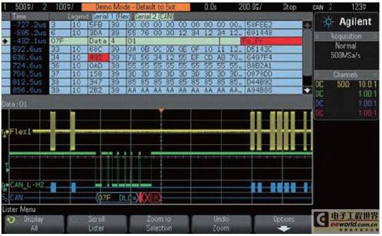
Figure 1 shows an Agilent 3000 X-Series oscilloscope simultaneously capturing and decoding CAN and FlexRay buses. At the bottom of the display are time-correlated decode traces for each bus, below the captured physical layer waveforms. The top half of the oscilloscope display shows the industry's only time-interleaved "lister" display, sometimes called an event table. This data format is closer to that of a traditional protocol analyzer.
Previous article:Principle and implementation of common test pattern generator for serial bus
Next article:32 Gbps High-Speed SerDes Mass Production Test Solution
Recommended ReadingLatest update time:2024-11-22 15:19


- Popular Resources
- Popular amplifiers
-
 New Energy Vehicle Control System Inspection and Maintenance (Edited by Bao Pili)
 -
 Detailed explanation of big data technology system: principles, architecture and practice (Dong Xicheng)
 -
 Automotive CAN embedded intrusion detection system based on deep learning
 -
 Lightweight FPGA-based IDS-ECU architecture for automotive CAN networks
- New IsoVu™ Isolated Current Probes: Bringing a New Dimension to Current Measurements
- Modern manufacturing strategies drive continuous improvement in ICT online testing
- Methods for Correlation of Contact and Non-Contact Measurements
- Keysight Technologies Helps Samsung Electronics Successfully Validate FiRa® 2.0 Safe Distance Measurement Test Case
- From probes to power supplies, Tektronix is leading the way in comprehensive innovation in power electronics testing
- Seizing the Opportunities in the Chinese Application Market: NI's Challenges and Answers
- Tektronix Launches Breakthrough Power Measurement Tools to Accelerate Innovation as Global Electrification Accelerates
- Not all oscilloscopes are created equal: Why ADCs and low noise floor matter
- Enable TekHSI high-speed interface function to accelerate the remote transmission of waveform data
- Intel promotes AI with multi-dimensional efforts in technology, application, and ecology
- ChinaJoy Qualcomm Snapdragon Theme Pavilion takes you to experience the new changes in digital entertainment in the 5G era
- Infineon's latest generation IGBT technology platform enables precise control of speed and position
- Two test methods for LED lighting life
- Don't Let Lightning Induced Surges Scare You
- Application of brushless motor controller ML4425/4426
- Easy identification of LED power supply quality
- World's first integrated photovoltaic solar system completed in Israel
- Sliding window mean filter for avr microcontroller AD conversion
- What does call mean in the detailed explanation of ABB robot programming instructions?
- USB Type-C® and USB Power Delivery: Designed for extended power range and battery-powered systems
- RAQ #223: How to measure and determine soft-start timing without a soft-start equation?
- RAQ #223: How to measure and determine soft-start timing without a soft-start equation?
- GigaDevice's full range of automotive-grade SPI NOR Flash GD25/55 wins ISO 26262 ASIL D functional safety certification
- GigaDevice's full range of automotive-grade SPI NOR Flash GD25/55 wins ISO 26262 ASIL D functional safety certification
- New IsoVu™ Isolated Current Probes: Bringing a New Dimension to Current Measurements
- New IsoVu™ Isolated Current Probes: Bringing a New Dimension to Current Measurements
- Infineon Technologies Launches ModusToolbox™ Motor Kit to Simplify Motor Control Development
- Infineon Technologies Launches ModusToolbox™ Motor Kit to Simplify Motor Control Development
- STMicroelectronics IO-Link Actuator Board Brings Turnkey Reference Design to Industrial Monitoring and Equipment Manufacturers
- LVDS Receive
- Buy or rent Lark Board
- Anti-interference design of digital circuit
- Create a GD32VF103 project using Visual Studio Code
- How to measure AC signals
- LTC4291/92 PSE controller chipset leads the way
- European IPTV enters large-scale commercial use, with Chinese operators catching up
- Circuit Playground Star Tree
- Image Algorithm Transplantation to DSP and Its Optimization Steps
- The market size of body electronics semiconductors exceeds 1.6 billion yuan


 New Energy Vehicle Control System Inspection and Maintenance (Edited by Bao Pili)


 京公网安备 11010802033920号