rapid popularization and application of composite materials have put forward higher and higher requirements for the inspection of composite materials and products. In recent years, the continuous updating and rapid development of radiographic inspection methods have improved the radiographic inspection capability and inspection range to varying degrees. Due to the characteristics of intuitive images and easy preservation, radiographic inspection is still one of the most direct and effective inspection methods for non-destructive inspection of composite materials. It judges the different absorption or scattering characteristics of the radiation and the quality, size, characteristics, etc. of the inspected workpiece based on the different components, density, thickness, etc. of the inspected workpiece. Real
-time imaging inspection technology is
an electronic imaging method in which the image changes rapidly with the change of the imaging object, that is, the inspection method in which the generated image can be observed while the transillumination is being performed [1]. Figure 1 shows a schematic diagram of the real-time imaging inspection system.

When a beam of X-ray with uniform intensity is irradiated through an object, if there are defects or structural differences in a local area of the object, it will change the attenuation of the object to the radiation, making the intensity of the transmitted radiation different in different parts. In this way, by using a certain detector to detect the intensity of the transmitted radiation, it is possible to determine the defects inside the object and the distribution of the object [1].
2 Characteristics of X-ray real-time imaging inspection technology
The main advantage of X-ray real-time imaging inspection technology is dynamic and rapid inspection. It uses scintillation crystals or fluorescent materials and photomultipliers to form a detector to pick up signals and directly obtain a digital image, which can be used for near-real-time quality assessment [1].
Practical application of X-ray real-time imaging inspection technology in composite blade inspection
1 Shortened the inspection time of composite blades and greatly improved work efficiency
Compared with the inspection of composite blades using radiographic inspection technology, the inspection of composite blades using real-time imaging inspection technology shortens the inspection time and improves work efficiency. This is mainly reflected in two aspects:
(1) It saves film cutting, packaging time and film darkroom processing time.
The film cutting, packaging and darkroom processing time required for each composite blade tested by radiographic inspection technology is at least 140 minutes, while the real-time radiographic imaging inspection technology does not require film.
(2) The inspection time is shortened.
Composite materials are low-density materials. When using radiographic inspection technology to inspect composite blades, in order to obtain a better quality film, only when the radiation can penetrate the parts can a lower energy be selected and a larger exposure be used to inspect the composite blades. In this way, a better quality radiographic film with a clear image can be obtained. Based on an average of 40 times of exposure per blade, it takes 240 minutes to expose one blade. When using real-time radiographic imaging inspection technology, when the parts are inspected, the signal obtained by the radiation converter is sent to the image processing part after A/D conversion (or has been directly digitized) to improve the image quality through image data processing; and the inspection process of the entire real-time radiographic imaging inspection system is controlled through computers, software and some auxiliary equipment (such as monitors, cameras, etc.). In this way, the image is formed each time in about 6 seconds, which greatly improves work efficiency.
2 Reduced costs and saved energy
Compared with the X-ray real-time imaging inspection technology, the use of radiographic inspection technology to inspect composite blades requires the use of film. The average film cost for each composite blade is at least 560 yuan. Based on the inspection of 20 composite blades, the required film cost is at least 11,200 yuan. In addition, the exposed film needs to be processed in a darkroom, and a certain amount of film processing solution costs are required during the process. When using X-ray real-time imaging inspection technology to inspect composite blades, it is only necessary to store the obtained image in a computer or store it in a CD after burning. Each CD costs about 10 yuan, and each CD can store at least 20 blade images.
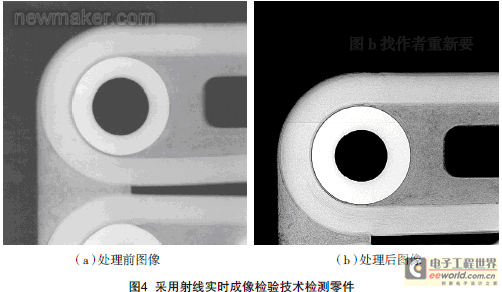
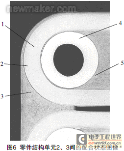
3 The image display of the matching state of each structural unit of the part is clearer and the inspection effect is better
. Generally speaking, the manufacturing process of composite parts is different from that of metal parts, and their internal defects are also closely related to the manufacturing process. Different manufacturing processes will also produce different defects. Winding and laying are common processes for manufacturing components. Therefore, when selecting a transillumination method, the characteristics of defects that may be caused by the processing technology or forming process of the workpiece should be considered, and the direction that is most conducive to discovering defects should be selected for transillumination [1].
The transillumination methods for composite materials include: vertical transillumination (i.e., the transillumination method in which the central ray beam is perpendicular to the workpiece), parallel transillumination (i.e., the transillumination method in which the central ray beam is parallel to the axis of the conical part or the laying direction of the workpiece), tangent transillumination (i.e., the transillumination method in which the central ray beam is tangent to the arc surface of the conical part, cylindrical part, and tubular part), and oblique transillumination (i.e., the transillumination method in which the central ray beam is at a certain angle to the central axis of the cylindrical part and the container part) [2].

Figure 2 Vertical transillumination method

Figure 3 Parallel transillumination method


Figure 5: Parts inspected using radiographic inspection technology

Radiation, commonly known as rays. For industrial ray detection technology, the main problem faced in radiation protection is external irradiation protection. When radiation acts on a living organism, it will cause damage to the organism's cells, tissues, quality control, etc. due to ionization, causing pathological reactions and producing radiation biological effects. [page]

Figure 7 Negative display of an image
(1) Time. Reducing the exposure time can reduce the exposure dose received. When the exposure rate is constant, since:
dose = dose rate × time, (1) Therefore, the allowable exposure time can be determined according to the size of the exposure rate.
(2) Distance. If the radiation source is regarded as a point source, the radiation dose at a point in the radiation field is inversely proportional to the square of the distance between the point and the source, that is: D1/D2=F12/F22, (2) where F1 is the distance between the source and point 1 in the radiation field; F2 is the distance between the source and point 2 in the radiation field; D1 is the radiation dose at point 1 in the radiation field; D2 is the radiation dose at point 2 in the radiation field; thus, increasing the distance will rapidly reduce the radiation dose.

Figure 8: Positive display of an image
By taking the above methods, the possible harm of radiation to the human body can be minimized. When using real-time imaging inspection technology to detect composite blades, since the equipment uses a "steel-lead-steel" structure to shield the radiation, and has been tested by relevant qualification departments, the radiation leakage of the equipment meets the GB18871-2002 standard, and the operator can safely perform the inspection operation. In this way, the operator can not only operate the equipment with confidence, but also observe the object to be inspected at any time through the lead glass at a close distance when the X-ray machine emits radiation, and adjust the position and direction of the object to be inspected at any time.
Conclusion
With the continuous deepening of composite X-ray inspection, real-time imaging inspection technology will play an increasingly important role, laying a solid foundation for the development and further research of composite blades.
References
[1] Zheng Shicai. Radiographic Testing, Beijing: Machinery Industry Press, 2004.
[2] 703rd Research Institute, First Academy of China Aerospace Science and Technology Corporation. FL9360 Nondestructive Testing Methods for Fiber Reinforced Composite Materials, Part 2. X-ray Photographic Inspection. (end)
Previous article:Nondestructive testing technology of honeycomb sandwich structure
Next article:Discussion on the Principle and Selection of Flow Meters Commonly Used in Chlor-alkali Plants
- Popular Resources
- Popular amplifiers
- From probes to power supplies, Tektronix is leading the way in comprehensive innovation in power electronics testing
- Seizing the Opportunities in the Chinese Application Market: NI's Challenges and Answers
- Tektronix Launches Breakthrough Power Measurement Tools to Accelerate Innovation as Global Electrification Accelerates
- Not all oscilloscopes are created equal: Why ADCs and low noise floor matter
- Enable TekHSI high-speed interface function to accelerate the remote transmission of waveform data
- How to measure the quality of soft start thyristor
- How to use a multimeter to judge whether a soft starter is good or bad
- What are the advantages and disadvantages of non-contact temperature sensors?
- In what situations are non-contact temperature sensors widely used?
- LED chemical incompatibility test to see which chemicals LEDs can be used with
- Application of ARM9 hardware coprocessor on WinCE embedded motherboard
- What are the key points for selecting rotor flowmeter?
- LM317 high power charger circuit
- A brief analysis of Embest's application and development of embedded medical devices
- Single-phase RC protection circuit
- stm32 PVD programmable voltage monitor
- Introduction and measurement of edge trigger and level trigger of 51 single chip microcomputer
- Improved design of Linux system software shell protection technology
- What to do if the ABB robot protection device stops
- Learn ARM development(14)
- Learn ARM development(15)
- Analysis of the application of several common contact parts in high-voltage connectors of new energy vehicles
- Wiring harness durability test and contact voltage drop test method
- From probes to power supplies, Tektronix is leading the way in comprehensive innovation in power electronics testing
- From probes to power supplies, Tektronix is leading the way in comprehensive innovation in power electronics testing
- Sn-doped CuO nanostructure-based ethanol gas sensor for real-time drunk driving detection in vehicles
- Design considerations for automotive battery wiring harness
- Do you know all the various motors commonly used in automotive electronics?
- What are the functions of the Internet of Vehicles? What are the uses and benefits of the Internet of Vehicles?
- 【GD32307E-START】DAC+ADC test
- EZ-BLE PRoC Low Power Bluetooth Module Introduction
- Can someone help me analyze what this circuit does?
- Ding~ You have a review information waiting to be received~ Please open this post to view
- Simple stopwatch based on MSP430f149 MCU
- Op amp circuit waveform analysis problem
- [GD32E231 DIY Contest]——08. Solution to using JLINK to debug and download GD32E231
- Recruiting hardware test engineers Annual salary: 200,000-500,000 | Experience: more than 5 years | Work location: Shenzhen
- When should you choose DC/DC and when should you choose LDO?
- Share: TI headphone amplifier positive and negative voltage design

 ALD2706SA


 京公网安备 11010802033920号